Eureka AIR delivers breakthrough ideas for toughest innovation challenges, trusted by R&D personnel around the world.

Optical path performance testing system for fiber optic gyroscope

A test system, fiber optic gyroscope technology, applied in the field of fiber optic inertial navigation, can solve the problems of easily damaged components, interferometer optical path, total loss of optical path cannot be tested, improper operation, etc.

Active Publication Date: 2020-10-20
BEIJING AEROSPACE TIMES OPTICAL ELECTRONICS TECH
View PDF5 Cites 0 Cited by
  • Summary
  • Abstract
  • Description
  • Claims
  • Application Information

AI Technical Summary

Problems solved by technology

[0004] The optical path loss test method in the prior art is: for the light source power test, the light source needs to be connected to the light source driving device first, and then the optical power output is tested with the help of an optical power meter; , and then connect the test light source to the device under test, and then connect the test light source to the light source driving device, and then test the output optical power of the device under test. This method is complicated to test and may damage the device if it is improperly operated.
However, it is impossible to test the optical path of the interferometer and the total loss of the optical path

Method used


Image

  • Optical path performance testing system for fiber optic gyroscope
  • Optical path performance testing system for fiber optic gyroscope

Examples


Embodiment

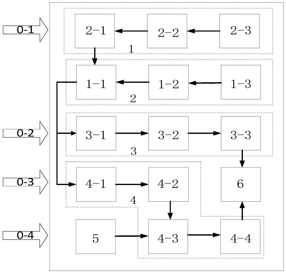
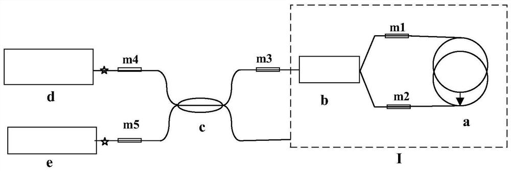
[0034] An optical path performance test system for a fiber optic gyroscope, comprising a light source output drive module 1, a light source output module 2, an optical power test module 3, an interferometer optical path loss test module 4, a detector voltage detection module 5 and a data processing display module 6. The optical fiber gyro optical path under test is as follows: figure 2 shown.

[0035] The fiber optic gyro optical path includes a fiber ring a, a Y waveguide b, a coupler c, a light source d and a detector e, and the pigtails of the above components are connected through fusion points at m1-m5. The optical path formed by connecting the fiber ring a and the Y waveguide b through the fusion points at m1 and m2 is called the interferometer optical path I.

[0036] The light source output driving module 1 provides a light source driving current interface, which can be connected to the light source 1-1 and the external light source 0-1, and realizes constant tempera...


PUM


Abstract

The invention discloses an optical path performance testing system for a fiber-optic gyroscope. The optical path performance testing system comprises a light source output driving module (1), a lightsource output module (2), an optical power testing module (3), an interferometer optical path loss testing module (4), a detector voltage detection module (5) and a data processing display module (6).The system can realize testing of light source output optical power, connection loss of couplers or Y waveguides or optical fiber rings or interferometers and total loss of optical paths, and has theadvantages of easiness in operation, high accuracy, automatic display of results, and convenience for detection of the loss of an optical fiber fusion process.

Description

technical field [0001] The invention relates to an optical path performance testing system for an optical fiber gyroscope, which belongs to the technical field of optical fiber inertial navigation. Background technique [0002] As a new type of inertial instrument, fiber optic gyroscope has been widely used in missiles, aircraft, ships and vehicles due to its advantages in accuracy, power consumption and quality. [0003] With the wide application of fiber optic gyroscopes, the number and types of fiber optic gyroscopes are also increasing. At present, more and more gyroscopes are entering the mass production stage. Due to optical fiber cleaning, improper cutting, or welding errors, optical fiber mismatch, etc., the optical path loss problem often occurs after assembly of the optical fiber gyroscope, which affects the accuracy of the optical fiber gyroscope and requires rework. , affecting production efficiency, and improper operation during repairing can also lead to optic...

Claims


Application Information

Patent Timeline
Patent Type & Authority Patents(China)
IPC IPC(8): G01C25/00
CPCG01C25/005
Inventor 许保祥于海成张志永王利超冯文帅李德桥吴旭东
Owner BEIJING AEROSPACE TIMES OPTICAL ELECTRONICS TECH
Why Eureka
Eureka Blog
Learn More