Electric power testing socket

A technology of test seat and electric power, which is applied in the direction of the measuring device shell, etc., can solve the problems of short service life and poor structural strength, and achieve the effect of long service life, strong corrosion resistance and reasonable design

Pending Publication Date: 2018-12-21
ZHEJIANG DEQING CONCEPTFE PLASTIC PROD
0 Cites 0 Cited by

AI-Extracted Technical Summary

Problems solved by technology

[0002] On the power test device, it is necessary to use a power test stand to separate the cables, but the...

Abstract

The invention belongs to the technical field of electric power testing components, and particularly relates to an electric power testing socket. The electric power testing socket comprises a cylindrical socket body made of polytetrafluoroethylene, one end of the socket body is opening and the other end of the socket body is closed, a locating ring is arranged far away from the opening end on the socket body, the locating ring and the socket body are connected to form an integrated structure, fixed holes evenly distributed along a peripheral direction is arranged on the locating ring, a middlepart of an end plate of the socket body is provided with an isolating tube, the isolating tube is arranged in a manner of being coaxial with the socket body, the end plate and the isolating tube are connected to form the integrated structure, at least two isolating plates evenly distributed along the peripheral direction are arranged between the isolating tube and the socket body, the isolating plates are respectively connected with the end plate and the socket body to form integrated structures, axial length of the isolating plate and the isolating tube is adaptive to the socket body, the endplate between two neighboring isolating plates in peripheral direction is provided with two first wire holes, and three second wire holes encircling in the isolating tube penetrate through the end plate. Compared with the prior art, the electric power testing socket has the advantages of rational design, firm structure and long service life.

Application Domain

Measurement instrument housing

Technology Topic

Axial lengthRational design +2

Image

  • Electric power testing socket
  • Electric power testing socket

Examples

  • Experimental program(1)

Example Embodiment

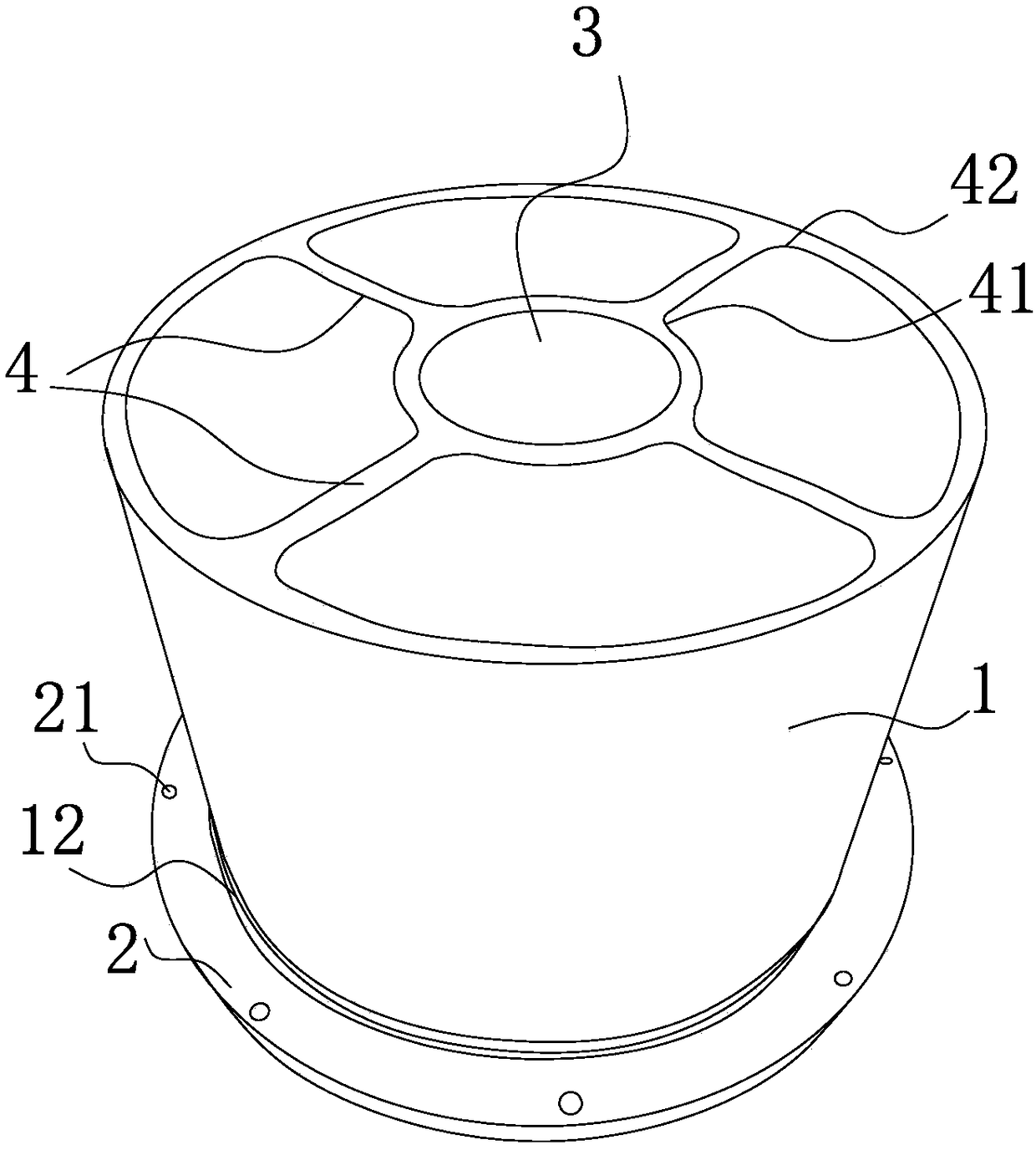
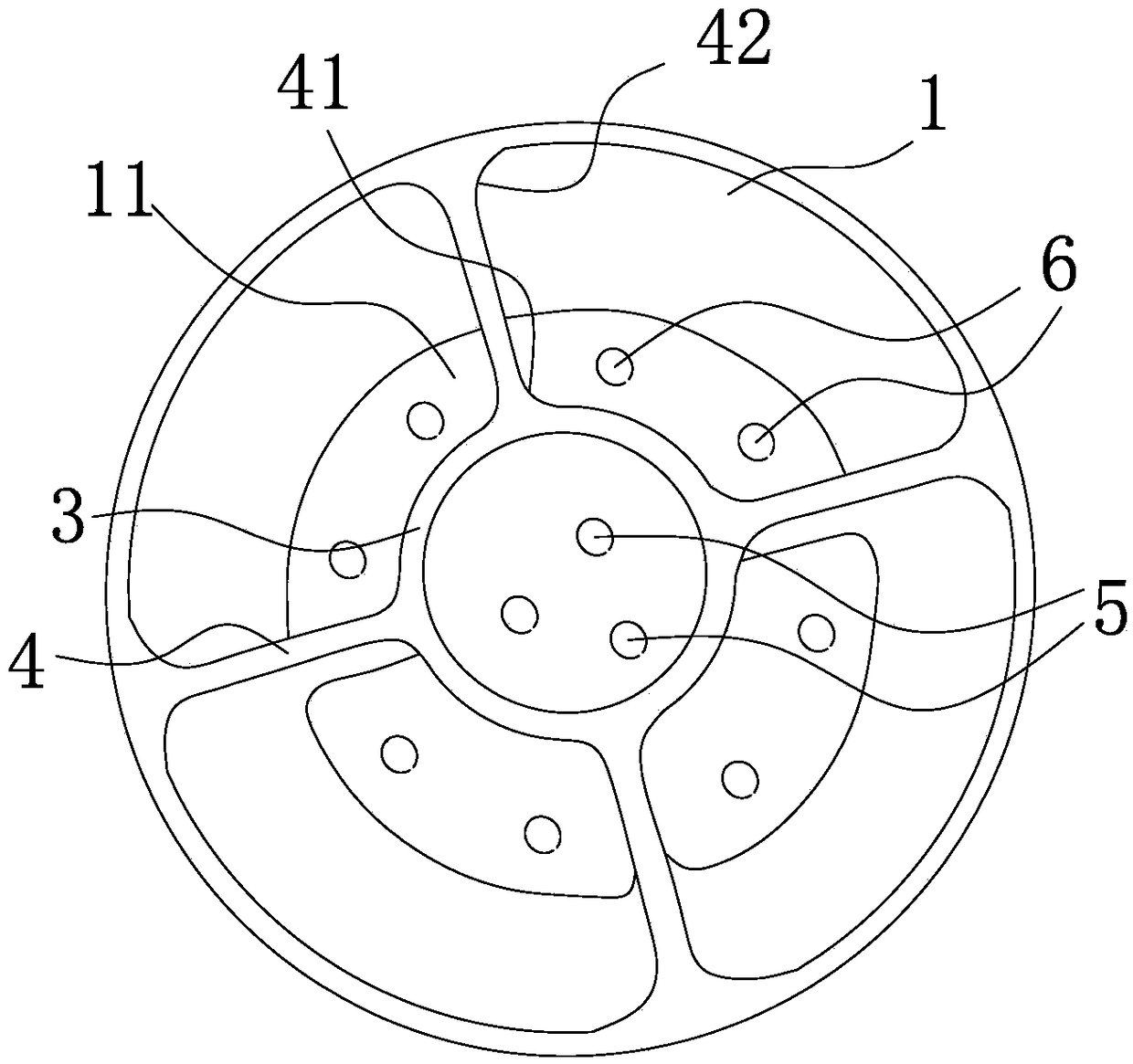
[0013] like figure 1 , 2 As shown, the electric test seat includes a cylindrical seat body 1 with one end open and one end closed and made of polytetrafluoroethylene. The seat body 1 is provided with a positioning ring 2 on the end far away from the opening, and the positioning ring 2 is connected to the seat body 1. One-piece structure, the positioning ring 2 is provided with fixing holes 21 evenly distributed along the circumferential direction, the middle part of the end plate 11 of the base body 1 is provided with an isolation tube 3, the isolation tube 3 is coaxially arranged with the base body 1 and the end The plate 11 is connected to the isolation tube 3 in an integrated structure, and at least two isolation plates 4 are evenly distributed along the circumferential direction between the isolation tube 3 and the base body 1, and the isolation plates 4 are connected to the end plate 11 and the base body 1 respectively. Integral structure, the axial length of the isolation plate 4 and the isolation tube 3 is adapted to the seat body 1, two first wire holes 5 are opened on the end plate 11 between the two adjacent isolation plates 4 in the circumferential direction, and the end plate 11 also runs through three second wire holes 6 enclosed in the isolation tube 3 . The positioning ring 2, the isolation tube 3, the isolation plate, the first arc-shaped reinforcing part, the second arc-shaped reinforcing part 42, and the annular reinforcing rib 12 are all made of polytetrafluoroethylene.
[0014] More specifically, four isolation plates 4 are evenly distributed along the circumferential direction between the isolation tube 3 and the base body 1 .
[0015] In order to enhance the firmness of the structure, first arc-shaped reinforcements 41 are arranged axially between both sides of the inner end of the isolation plate 4 and the isolation tube 3, and the first arc-shaped reinforcements 41 are connected to the isolation plate 4 and the isolation tube 3. An integrated structure, between the two sides of the outer end of the isolation plate 4 and the isolation tube 3 are respectively provided with a second arc-shaped reinforcement 42 arranged in the axial direction, and the second arc-shaped reinforcement 42 is connected with the isolation plate 4 and the isolation tube 3 Integral structure; an annular reinforcing rib 12 is provided between the positioning ring 2 and the seat body 1, and the annular reinforcing rib is connected with the positioning ring 2 and the seat body 1 in an integral structure; the three second wire holes 6 are distributed in a triangular shape.
[0016] The specific embodiments described herein are merely illustrative of the spirit of the invention. Those skilled in the art to which the present invention belongs can make various modifications or supplements to the described specific embodiments or adopt similar methods to replace them, but they will not deviate from the spirit of the present invention or go beyond the definition of the appended claims range.
[0017] Although the seat body 1, the positioning ring 2, the isolation tube 3, the isolation plate 4, the end plate 11, the first wire hole 5, the first arc-shaped reinforcement 41, the second wire hole 6, and the second arc The terminology such as shaped reinforcing part 42, annular reinforcing rib 12, etc., does not exclude the possibility of using other terms. These terms are only used to describe and explain the essence of the present invention more conveniently, and it is against the spirit of the present invention to interpret them as any additional limitation.

PUM

no PUM

Description & Claims & Application Information

We can also present the details of the Description, Claims and Application information to help users get a comprehensive understanding of the technical details of the patent, such as background art, summary of invention, brief description of drawings, description of embodiments, and other original content. On the other hand, users can also determine the specific scope of protection of the technology through the list of claims; as well as understand the changes in the life cycle of the technology with the presentation of the patent timeline. Login to view more.

Similar technology patents

Stator assembly for asynchronous motor and method for making same

InactiveCN101043154AEasy to windreasonable design
Owner:GUANGDONG WELLING ELECTRIC MACHINE MFG

Novel flexible lead-radiation-free protective clothing

Owner:南京核安核能科技有限公司

Displacement-crawler-type pipe dredging robot

Owner:CHINA UNIV OF GEOSCIENCES (WUHAN)

Classification and recommendation of technical efficacy words

  • stable structure
  • reasonable design

Silicon/carbon composite microsphere negative electrode material as well as preparation method and application for same

ActiveCN103311522Astable structureImprove charge and discharge cycle life
Owner:INST OF PROCESS ENG CHINESE ACAD OF SCI

Preparation method of magnetic graphene based oil absorption foam material

Owner:XINJIANG TECHN INST OF PHYSICS & CHEM CHINESE ACAD OF SCI

Embedding accuracy control construction method for embedded part of overlong equipment foundation platform

InactiveCN102134879Areasonable designSimple construction steps
Owner:SCEGC NO 6 CONSTR ENG GRP CO LTD
Why Eureka
Try Eureka