
Novel quick multi-ring radio signal direction-finding algorithm

A radio signal and radio technology, which is used in direction finders using radio waves, radio wave direction/bias determination systems, etc., can solve problems such as loss of effectiveness, large hardware resources, and large time consumption.

Active Publication Date: 2018-12-21
成都宝通天宇电子科技有限公司
View PDF4 Cites 0 Cited by
  • Summary
  • Abstract
  • Description
  • Claims
  • Application Information

AI Technical Summary

Problems solved by technology

There are two ways to realize this operation: first, if a serial structure is used, it will take a lot of time, and the direction finding results will lose effectiveness; second, if a parallel structure is used, a lot of hardware resources will be spent

Method used


Image

  • Novel quick multi-ring radio signal direction-finding algorithm

Examples


Embodiment Construction

[0017] The present invention will be further described below with reference to the accompanying drawings, but the protection scope of the present invention is not limited to the following.

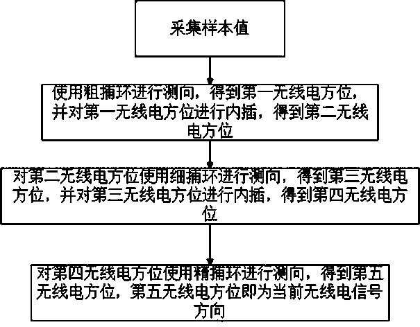
[0018] like figure 1 As shown, a multi-loop radio signal direction finding algorithm is characterized in that, the algorithm comprises the following steps:

[0019] The first step is to collect sample values;

[0020] The second step is to use the coarse capture ring for direction finding to obtain the first radio azimuth, and to interpolate the first radio azimuth to obtain the second radio azimuth;

[0021] The third step is to use the fine capture ring for direction finding on the second radio azimuth to obtain the third radio azimuth, and interpolate the third radio azimuth to obtain the fourth radio azimuth;

[0022] The fourth step is to use the fine-capturing ring for direction finding on the fourth radio azimuth to obtain the fifth radio azimuth, and the fifth radio azimuth is th...


PUM


Abstract

The invention relates to a multi-ring radio signal direction-finding algorithm. The algorithm comprising the following steps: step one, collecting a sample value; step two, carrying out direction finding by using a coarse capturing ring to obtain a first radio bearing direction and carrying out interpolation on the first radio bearing direction to obtain a second radio bearing direction; step three, carrying out direction finding on the second radio bearing direction by using a fined capturing ring to obtain a third radio bearing direction, and carrying out interpolation on the third radio bearing direction to obtain a fourth radio bearing direction; and step four, carrying out direction finding on the fourth radio bearing direction by using a refined capturing ring to obtain a fifth radiobearing direction being a current radio bearing direction. Therefore, a multi-ring radio signal direction-finding algorithm can be implemented.

Description

technical field [0001] The invention relates to the field of radio direction finding, in particular to a multi-loop radio signal direction finding algorithm. Background technique [0002] When using the correlation interferometer theory for direction finding, it is necessary to perform a correlation algorithm based on the currently measured phase difference and the sample to obtain the most relevant azimuth, which is the incoming wave azimuth. The azimuth step determines the accuracy of the incoming wave azimuth measured by the system. Take the index requirement of 1° as an example: the current phase difference and the phase difference of each degree of 360° in the sample are correlated to obtain the result. There are two ways to implement this operation: one, if a serial structure is used, it will take a lot of time, and the direction finding result will lose its effectiveness; the other, if a parallel structure is used, a lot of hardware resources will be spent. SUMMARY...

Claims


Application Information

Patent Timeline
Patent Type & Authority Applications(China)
IPC IPC(8): G01S3/14
CPCG01S3/14
Inventor 王文林丁健周香香
Owner 成都宝通天宇电子科技有限公司
Learn More