A radar photoelectric linkage system and its control method

A technology of linkage system and control method, which is applied in the direction of radio wave measurement system, radio wave reflection/reradiation, instruments, etc., and can solve the problems of high layout cost, control method and linkage accuracy.

Active Publication Date: 2021-02-26
YUSENSE INFORMATION TECH & EQUIP QINGDAO INC
View PDF12 Cites 0 Cited by
  • Summary
  • Abstract
  • Description
  • Claims
  • Application Information

AI Technical Summary

Problems solved by technology

[0004] The purpose of the present invention is to provide a radar photoelectric linkage system and its control method to solve the problems that the existing radar photoelectric linkage system has relatively high layout costs when performing large-angle detection, and the system control method and linkage accuracy have great limitations.

Method used


Image

  • A radar photoelectric linkage system and its control method
  • A radar photoelectric linkage system and its control method
  • A radar photoelectric linkage system and its control method

Examples


Embodiment Construction

[0043] In order to enable those skilled in the art to better understand the solution of the present invention, the present invention will be further described in detail below in conjunction with the accompanying drawings and specific embodiments. Apparently, the described embodiments are only some of the embodiments of the present invention, but not all of them. Based on the embodiments of the present invention, all other embodiments obtained by persons of ordinary skill in the art without making creative efforts belong to the protection scope of the present invention.

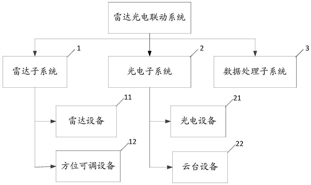
[0044] A structural block diagram of a specific embodiment of the radar photoelectric linkage system provided by the present invention is as follows figure 1As shown, the system includes: radar subsystem 1, optoelectronic system 2 and data processing subsystem 3;

[0045] Wherein, the radar subsystem 1 includes a radar device 11 and an azimuth-adjustable device 12; the radar device 11 is used for echo detecti...


PUM


Abstract

The invention discloses a radar photoelectric linkage system. The radar equipment is used for echo detection of targets in the radar detection area; the azimuth adjustable equipment is used for adjusting the detection azimuth. The photoelectric device is used to collect image signals in the field of view; the pan-tilt device is used to adjust the collection angle. The data processing subsystem is used to obtain the echo detection signal and image signal, realize the identification of the intrusion target according to the calculation of the echo detection signal and / or image signal, and send control instructions to the azimuth adjustable equipment and the pan-tilt equipment, In order to keep the intrusion target within the radar detection area and / or field of view area. This application can automatically or manually adjust the detection azimuth of the system according to the actual application scenarios and detection needs, so as to meet the expanded application of the azimuth detection area of ​​the system and effectively improve the azimuth utilization rate of the radar. In addition, the present invention also provides a control method of the radar photoelectric linkage system with the above-mentioned technical advantages.

Description

technical field [0001] The invention relates to the technical field of safety protection, in particular to a radar photoelectric linkage system and a control method thereof. Background technique [0002] With the increasing demand for security protection, various security measures are widely used in personal security, security facilities, prisons, coastline and border prevention and control, etc. Common security measures include man-made area patrol, photoelectric automatic cruise, electronic fence warning, and radar area detection. Various security measures can meet the work requirements of security area early warning, target intrusion tracking, and threat target disposal. However, due to its low response efficiency, no visual display, high layout cost and its own performance, operators cannot control the scene and the development of the situation in real time, accurately and effectively. [0003] The radar photoelectric linkage system can effectively make up for and impro...

Claims


Application Information

Patent Timeline
Patent Type & Authority Patents(China)
IPC IPC(8): G01S13/68
CPCG01S13/68
Inventor 刘春晖周学顺许英杰李先锋张军强
Owner YUSENSE INFORMATION TECH & EQUIP QINGDAO INC
Why Eureka
Try Eureka