
Numerical control tool assembly system based on motion control

An assembly system and motion control technology, which is applied to the device, material gluing, connecting components, etc. for coating liquid on the surface, which can solve the problems of affecting production and use efficiency, disconnection, and large reassembly, so as to solve the problem of labor cost and improve the The effect of quality and efficiency

Inactive Publication Date: 2022-01-21
TIANJIN SINO GERMAN VOCATIONAL TECHNICAL COLLEGE
View PDF0 Cites 0 Cited by
  • Summary
  • Abstract
  • Description
  • Claims
  • Application Information

AI Technical Summary

Problems solved by technology

Due to the high precision requirements of CNC tools, the use of this assembly method is likely to cause a disconnection between the CNC tool assembly production plan and the actual production requirements, thus seriously affecting the actual production efficiency.
In general, it takes a long time to use manual assembly, and there is a greater chance of reassembly
During the entire assembly process, the assembly work also requires the assembly personnel to have rich assembly experience, which leads to great limitations in the manual assembly method

Method used


Image

  • Numerical control tool assembly system based on motion control
  • Numerical control tool assembly system based on motion control
  • Numerical control tool assembly system based on motion control

Examples


Embodiment Construction

[0020] For the convenience of description, spatially relative terms may be used here, such as "on ...", "over ...", "on the surface of ...", "above", etc., to describe the The spatial positional relationship between one device or feature shown and other devices or features. It will be understood that the spatially relative terms are intended to encompass different orientations of the device in use or operation in addition to the orientation depicted in the figures. For example, if the device in the figures is turned over, devices described as "above" or "above" other devices or configurations would then be oriented "beneath" or "above" the other devices or configurations. under other devices or configurations". Thus, the exemplary term "above" can encompass both an orientation of "above" and "beneath". The device may be oriented differently, rotated 90 degrees, or at other orientations, and the spatially relative descriptions used herein interpreted accordingly.

[0021] Th...


PUM


Abstract

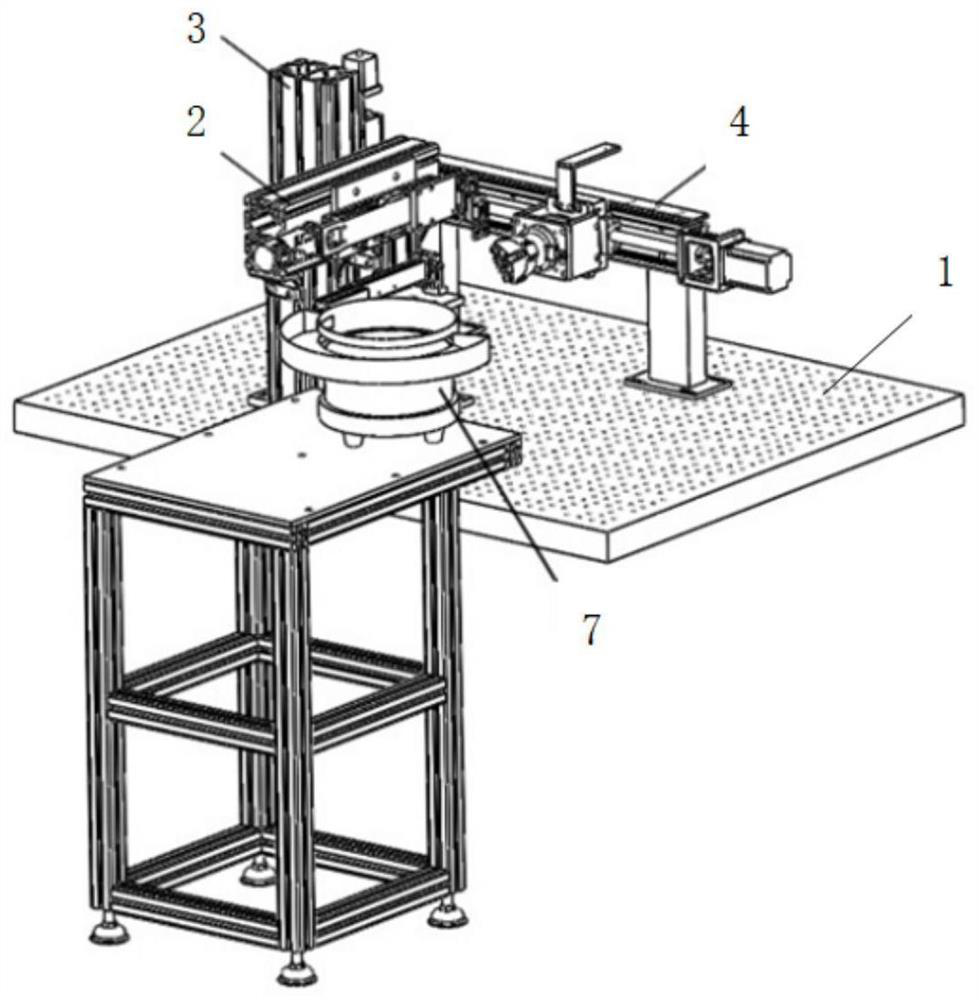
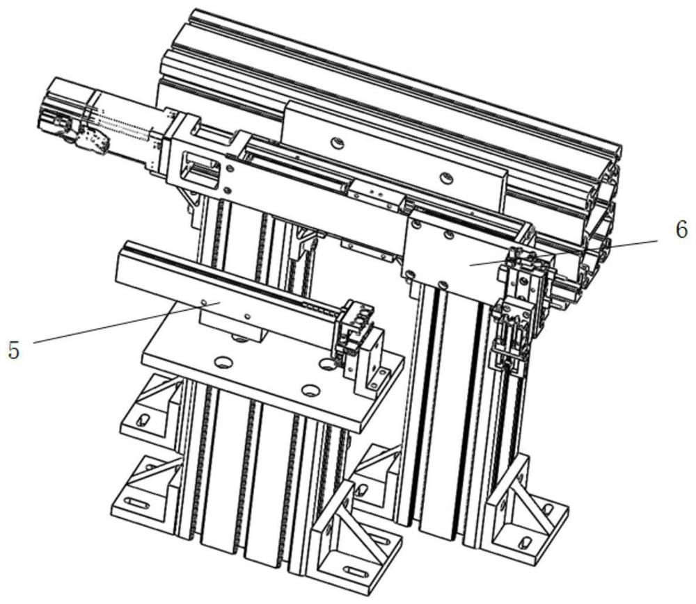
The invention relates to the technical field of automatic equipment production, in particular to a numerical control tool assembly system based on motion control. The system comprises a bottom plate, and a tool bit station, a gluing station and a gripper station which are fixed on the bottom plate, the gluing station is located on the rear side of the tool bit station, and the gripper station is located on one side of the gluing station and one side of the tool bit station. The tool bit station comprises a tool bit lifting assembly and a tool bit picking assembly located on one side of the tool bit lifting assembly. The gluing station comprises a glue tube motor, a glue bin, a glue tube and a glue tube descending cylinder. The gripper station comprises a moving module, a servo motor and a pneumatic gripper. The system not only solves the problem of labor cost of production, but also improves the quality and efficiency in the process of tool assembly.

Description

technical field [0001] The invention relates to the technical field of automatic equipment production, in particular to a motion control-based numerical control tool assembly system. Background technique [0002] In the production process of CNC cutting tools in many workshops in China, the manual assembly method has been adopted all the time. Due to the high precision requirements of CNC tools, the use of this assembly method is likely to cause a disconnect between the CNC tool assembly production plan and the actual production requirements, which seriously affects the actual production efficiency. In general, it takes a long time to use manual assembly, and the probability of reassembly is relatively high. During the entire assembly process, the assembly work also requires the assembly personnel to have rich assembly experience, which leads to great limitations in the manual assembly method. Contents of the invention [0003] In order to effectively solve the problems ...

Claims


Application Information

Patent Timeline
Patent Type & Authority Applications(China)
IPC IPC(8): B05C5/02B05C13/02F16B11/00
CPCB05C5/02B05C13/02F16B11/006
Inventor 范其明李云龙曾华鹏马玉策邸尧
Owner TIANJIN SINO GERMAN VOCATIONAL TECHNICAL COLLEGE
Learn More