Display panel and display device

A display panel and display device technology, applied in the direction of instruments, calculations, electrical digital data processing, etc., can solve the problems of UV glue coating thickness, affecting the bending angle of the bending area, etc., to reduce the bending stress and protect the bending area, improve the effect of bending angle

Active Publication Date: 2021-07-02
WUHAN CHINA STAR OPTOELECTRONICS SEMICON DISPLAY TECH CO LTD
View PDF6 Cites 0 Cited by
  • Summary
  • Abstract
  • Description
  • Claims
  • Application Information

AI Technical Summary

Problems solved by technology

[0005] Embodiments of the present invention provide a display panel and a display device; to solve the technical problem that the thicker UV glue coating on the bending area in the existing display panel and display device affects the bending angle of the bending area

Method used


Image

  • Display panel and display device
  • Display panel and display device
  • Display panel and display device

Examples


Embodiment Construction

[0047] Please refer to the drawings in the accompanying drawings, wherein like reference numerals refer to like components. The following description is based on illustrated specific embodiments of the invention, which should not be construed as limiting other specific embodiments of the invention not described in detail herein.

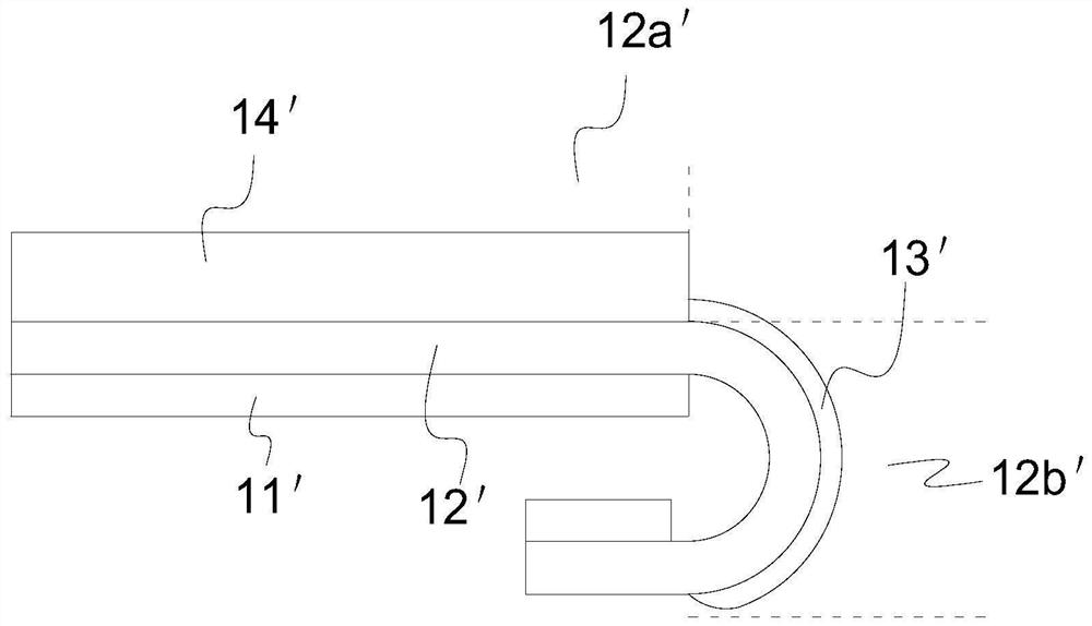
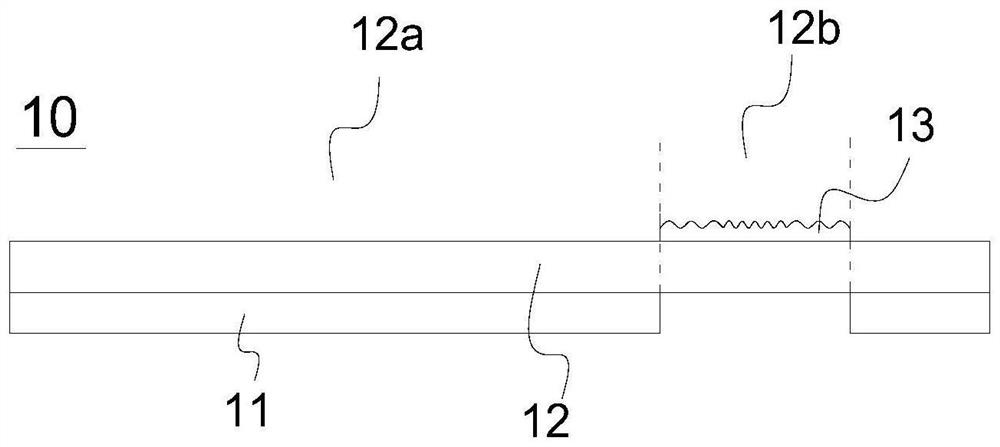
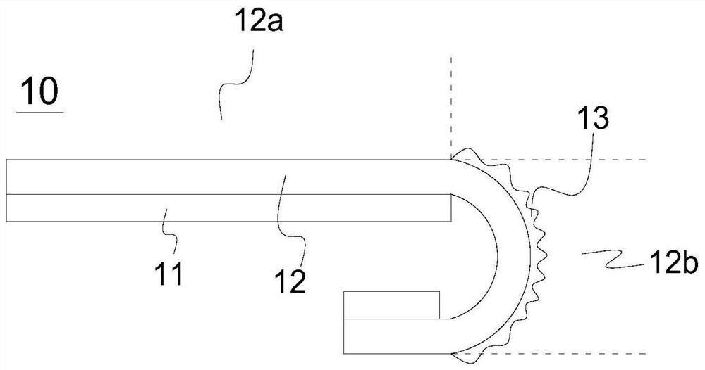
[0048] Please refer to Figure 2 to Figure 5 , figure 2 It is a schematic structural diagram in a flat state of the first preferred embodiment of the display panel of the present invention; image 3 It is a schematic structural diagram of the first preferred embodiment of the display panel in a bent state; Figure 4 It is a schematic structural view of the protective layer in the flat state of the first preferred embodiment of the display panel of the present invention; Figure 5 It is a structural schematic diagram of the protective layer in a bent state of the first preferred embodiment of the display panel of the present invention.

[0049] T...


PUM


Abstract

The present invention provides a display panel and a display device, which include a protective layer disposed on the bending area of ​​a flexible substrate. The bending stress is bounded by two adjacent protrusions to form a stress relief groove. In the present invention, the main body of the protective layer covers the bending area to protect the bending area, and reduces the bending stress in the bending area through the stress release groove of the protective layer.

Description

technical field [0001] The present invention relates to a display technology, in particular to a display panel and a display device. Background technique [0002] With the development of display technology, display devices are developing toward narrow frame and frameless directions. There is an increasing demand for widescreen display devices. [0003] Existing narrow bezel display devices, such as figure 1 , which includes a display panel, a touch panel 14' disposed on the display panel, and a polarizer disposed on the touch panel, the display panel includes a backplane 11' and a flexible substrate 12' disposed on the backplane 11', the flexible The substrate 12' includes a functional area 12a' for displaying patterns, a bending area 12b' set on the side of the functional area 12a' for bending, and a bending area 12b' set on the side of the bending area 12b' for binding the driver chip the binding region. When designing a narrow frame, the bending area 12b' is usually b...

Claims


Application Information

Patent Timeline
Patent Type & Authority Patents(China)
IPC IPC(8): G06F3/041
CPCG06F3/041
Inventor 茅健健
Owner WUHAN CHINA STAR OPTOELECTRONICS SEMICON DISPLAY TECH CO LTD
Why Eureka
Try Eureka