A steam turbine generator set
A technology for turbogenerator sets and machine bases, which is applied in the direction of electric components, electromechanical devices, electrical components, etc., and can solve problems such as unsatisfactory effects, inflexible heat dissipation of turbogenerators, poor sealing of turbogenerators, etc. , to prevent the effect of overheating
- Summary
- Abstract
- Description
- Claims
- Application Information
AI Technical Summary
Problems solved by technology
Method used
Image

Examples
Embodiment 1
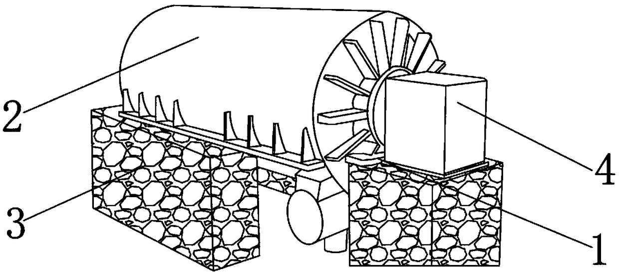
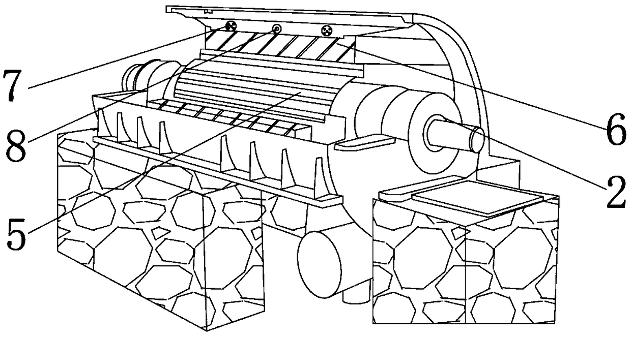
[0029] Such as Figure 1-7 As shown, a steam turbine generator set includes a device main body 1, and the device main body 1 includes a machine base 2, a concrete foundation 3 and a brush box 4, and the brush box 4 is fixedly installed on the front end of the machine base 2, and the brush box 4 Both are fixedly installed on the concrete foundation 3 with the base 2, the base 2 includes a rotor core 5, a stator core 6, a hydrogen cooler 7 and a temperature control device 8, and the rotor core 5 is inserted into the stator core 6, two hydrogen coolers 7 are fixedly installed on the inner shell of the machine base 2, and a temperature control device 8 is fixedly installed in the middle of the two hydrogen coolers 7.
[0030] The principle of the present invention: the base 2 is fixed on the concrete foundation 3, and the steam turbine is used as the prime mover to drag the rotor core 5 to rotate, cut the magnetic field of the stator core 6, generate electromagnetic induction, and...
Embodiment 2
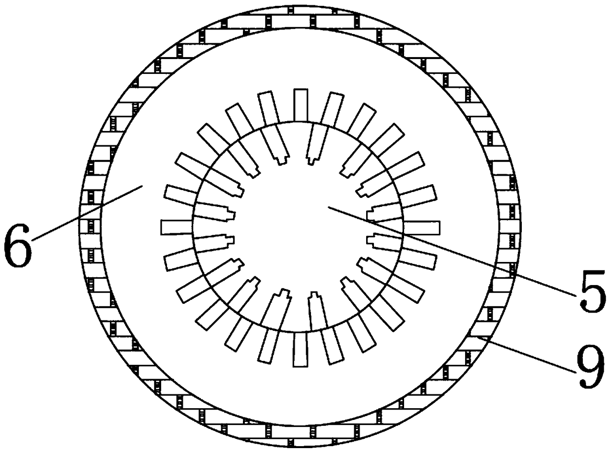
[0032] Such as Figure 1-7 As shown, a turbogenerator set, the stator core 6 wraps the concrete foundation 3 to live on the rotor core 5, and there is an air gap 14 between the stator core 6 and the rotor core 5, and the outer surface of the stator core 6 A stator coil 12 is wound on the surface, and a stator slot wedge 10 is fixedly installed on the lower end of the stator core 6, and a rotor coil 13 is wound on the outer surface of the rotor core 5, and a rotor ventilation slot is provided at the lower end of the rotor core 5 15, and the upper end of the rotor core 5 is fixed with a rotor slot wedge 11, the stator slot wedge 10 and the rotor slot wedge 11 can fix the stator core 6 and the rotor core 5, and the gap between the stator core 6 and the rotor core 5 An air gap 14 is left, and the lower end of the rotor core 5 is provided with a rotor ventilation slot 15, which can guide the hydrogen into the gap between the stator and the rotor, which is helpful for the ventilatio...
Embodiment 3
[0035] Such as Figure 1-7 As shown, a turbogenerator set, the middle of the hydrogen cooler 7 is provided with a nozzle 19, and the rear end connection port of the nozzle 19 is fixedly equipped with a solenoid valve 20, and the solenoid valve 20 can control the flow rate of hydrogen passing through the nozzle 19 size;
[0036]The temperature control device 8 includes a temperature sensor 21 and a temperature sensitive meter 23. Through the temperature control device 8 provided, the temperature inside the base 2 can be measured more sensitively, thereby more accurately controlling the solenoid valve in the hydrogen cooler 7 20. Accurately adjust the temperature in the machine base 2 within a reasonable range. The temperature sensor 21 is provided with a thermocouple wire 22 inside, and the temperature sensitive meter 23 includes a permanent magnet 24, a coil 25 and a tension wire 26. The inside of the temperature sensitive meter 23 is fixedly installed with a permanent magnet...
PUM
 Abstract
Description
Claims
Application Information
 - R&D Engineer
- R&D Manager
- IP Professional
- Industry Leading Data Capabilities
- Powerful AI technology
- Patent DNA Extraction
Browse by: Latest US Patents, China's latest patents, Technical Efficacy Thesaurus, Application Domain, Technology Topic.
© 2024 PatSnap. All rights reserved.Legal|Privacy policy|Modern Slavery Act Transparency Statement|Sitemap