Elevator car roof device

A technology for elevator car and car roof, which is applied to the suspension devices of wing fans, elevators in buildings, ceilings, etc., can solve problems such as difficulty in changing the appearance, achieve good visual modifiability, and improve the effect of visual appearance.

Active Publication Date: 2020-11-10
KONE CORP
View PDF9 Cites 0 Cited by
  • Summary
  • Abstract
  • Description
  • Claims
  • Application Information

AI Technical Summary

Problems solved by technology

This makes it difficult to change the appearance of the gap between the ceiling 101 and the top part of the wall 102

Method used


Image

  • Elevator car roof device
  • Elevator car roof device
  • Elevator car roof device

Examples


Embodiment Construction

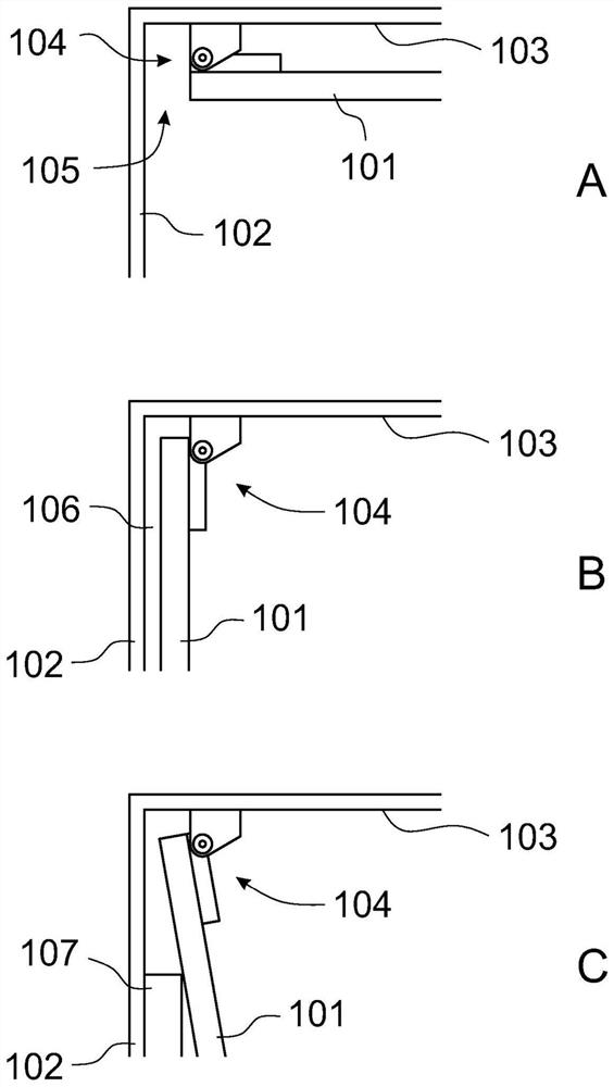
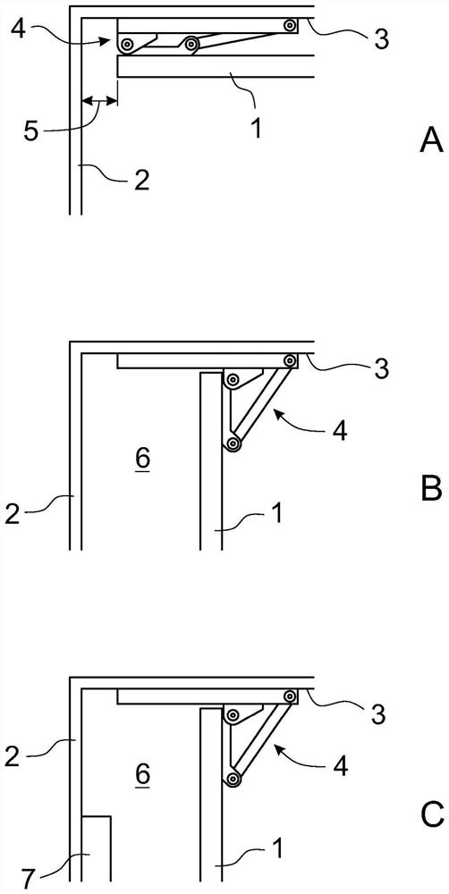
[0017] figure 2 A schematic, simplified and sectional view of a roof arrangement of an elevator according to the invention is shown. In the roof unit, figure 2 A side view of only one top corner of the elevator car is shown.

[0018] exist figure 2 In case A, the untreated roof 3 of the elevator car is covered with a ceiling 1 which is fixed to the untreated roof 3 by means of a hinge mechanism 4 according to the invention such that when the ceiling 1 is in its upper position, The nearest edge of the ceiling 1 is at a distance 5 from the inner surface of the first wall 2 of the elevator car. exist figure 2 In case B of the elevator car, the ceiling 1 of the elevator car is turned downward about the hinge axis of the hinge of the hinge mechanism 4 . Now, between the downwardly turned ceiling 1 and the inner surface of the first wall 2 there is a sufficiently wide gap 6, because due to the structure and function of the hinge mechanism 4, when the ceiling 1 is turned dow...


PUM


Abstract

The object of the invention is a roof arrangement for an elevator car in an elevator, comprising at least an elevator car, in which an untreated roof (3) and a wall (2), and In this elevator car is the ceiling (1) hinged to the untreated car roof (3). The ceiling (1) is hinged to the untreated roof (3) of the elevator car by means of a hinge mechanism (4) comprising a hinge mechanism (9) which is arranged in the ceiling (1) The second end of the ceiling is turned downwards while pulling the first end of the ceiling (1) away from the wall (2) of the elevator car.

Description

technical field [0001] The object of the invention is a roof arrangement for an elevator car. [0002] The roof arrangement for an elevator car according to the invention is particularly suitable for covering the interior untreated roof of an elevator car with a visually decorative ceiling fixed to the untreated roof in a hinged manner so that the free edge of the ceiling can It is easily lowered downwards by means of a hinge, in which case the passage opens to the elevator installation above the ceiling. Background technique [0003] In prior art hinge arrangements for ceilings of elevator cars, common hinges are generally used, with which the ceiling is fixed to the untreated roof of the elevator car. One such solution is in figure 1 is shown in , where facets A-C describe different situations. exist figure 1 In the case A of the elevator car, the untreated car roof 103 of the elevator car is covered with a ceiling 101, and the ceiling 101 is fixed to the untreated car...

Claims


Application Information

Patent Timeline
Patent Type & Authority Patents(China)
IPC IPC(8): B66B11/02E05D15/44E04B9/00
CPCE05D15/44E05Y2900/104E04B9/003E04B9/366B66B11/0226E04B9/00E05D3/18E05D15/42
Inventor T.萨林
Owner KONE CORP
Why Eureka
Try Eureka