Check patentability & draft patents in minutes with Patsnap Eureka AI!

rotary generator

A generator and rotating shaft technology, applied to synchronous motors with stationary armatures and rotating magnets, etc., can solve problems such as increased resistance and achieve the effect of reducing cogging

Active Publication Date: 2020-08-14
宫林正仁郎
View PDF7 Cites 0 Cited by
  • Summary
  • Abstract
  • Description
  • Claims
  • Application Information

AI Technical Summary

Problems solved by technology

In addition, the drag force required to keep the rotor spinning continuously increases
Therefore, it is not possible to generate electricity from a small amount of rotational kinetic energy

Method used


Image

  • rotary generator
  • rotary generator
  • rotary generator

Examples


Embodiment Construction

[0038] Hereinafter, the present invention will be described in detail. In addition, descriptions of materials, methods, and numerical ranges described in this specification are not intended to be limited to these materials, methods, and numerical ranges, and are not intended to exclude the use of other materials, methods, and numerical ranges.

[0039] In the present invention, the first member refers to a member that is a flat, cylindrical, or other soft magnetic body. In addition, all or a part of the trajectory accompanying the rotation of the permanent magnet (hereinafter referred to as the rotation trajectory) must be included in the first member. In other words, the shape of the first member is not particularly limited as long as it includes all or a part of the rotation locus. In addition, the gap refers to the distance between the first member and the permanent magnet.

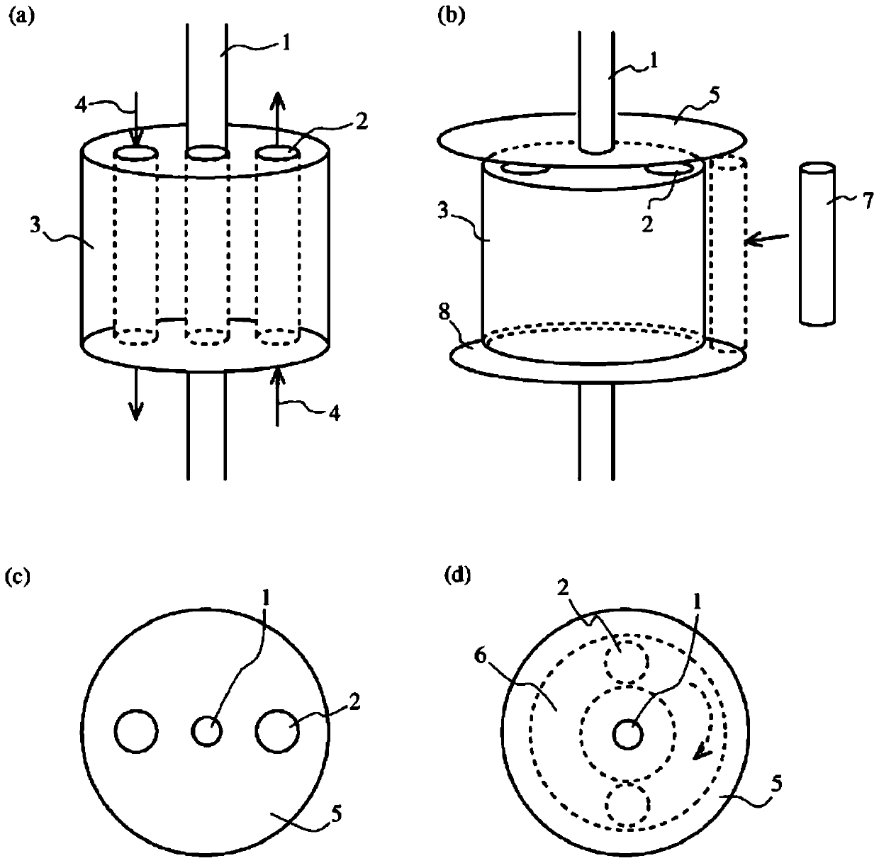
[0040] figure 1 It is a conceptual diagram of the generator of the present invention using a cyl...


PUM


Abstract

[Problem] To provide an electricity generator with which the generation of cogging torque can be reduced and electricity can be generated with less energy, and which enables more stable operation when electricity is being generated with varying wind power. [Solution] This rotary electricity generator includes a pair of planar first members comprising a soft magnetic material, and a plurality of cylindrical second members comprising a soft magnetic material. The first members are disposed in a state in which the planes of the first members intersect a longitudinal direction extension line of a permanent magnet of a rotor, with the permanent magnet and gaps interposed between the first members. The second members are disposed in such a way that the two ends of the cylinders thereof are in contact with the flat surfaces of the first members, and in such a way as to be parallel to the direction of an axis of rotation.

Description

technical field [0001] The present invention relates to a rotary generator in which a plurality of permanent magnets are used as a rotor to rotate and vibrate, and the magnetic flux generated by the permanent magnets is guided to an iron core on the stator side to induce electric power to a coil applied to the iron core. Background technique [0002] Traditional rotating electrical machines, such as generators, convert energy such as water power and fire power into rotational kinetic energy, and use the converted rotational kinetic energy to drive the generator and generate electricity. Generally used generators include a rotor with permanent magnets having N poles and S poles attached to a rotating shaft, an armature core having magnetic poles corresponding to the number of magnetic poles formed by the permanent magnets, and an armature core wound around the permanent magnets. The generator coil of the armature core rotates and drives the rotor to generate an AC magnetic fi...

Claims


Application Information

Patent Timeline
Patent Type & Authority Patents(China)
IPC IPC(8): H02K21/12
CPCH02K21/12
Inventor 宫林正仁郎
Owner 宫林正仁郎
Features
  • R&D
  • Intellectual Property
  • Life Sciences
  • Materials
  • Tech Scout
  • Unparalleled Data Quality
  • Higher Quality Content
  • 60% Fewer Hallucinations
Learn More