
Pilot signals

A pilot signal and link technology, applied in the field of pilot signals, can solve the problems of increased channel sensing, inaccuracy, etc.

Active Publication Date: 2018-12-21
SONY CORP
View PDF5 Cites 0 Cited by
  • Summary
  • Abstract
  • Description
  • Claims
  • Application Information

AI Technical Summary

Problems solved by technology

Typically, there is a trade-off between increased interference (for large transmit powers) and inaccuracy of channel sensing (for small transmit powers)

Method used


Image

  • Pilot signals
  • Pilot signals
  • Pilot signals

Examples


Embodiment Construction

[0056] Hereinafter, embodiments of the present invention will be described in detail with reference to the accompanying drawings. It should be understood that the following description of the embodiments is not to be considered in a limiting sense. The scope of the present invention is not intended to be limited by the embodiments described below or by the accompanying drawings, which are to be regarded as illustrative only.

[0057] The drawings are to be regarded as schematic representations and components illustrated in the drawings are not necessarily shown to scale. Rather, the various components are presented in such a manner that their function and general use will be apparent to those skilled in the art. Any connection or coupling between functional blocks, devices, components, or other physical or functional units shown in the figures or described herein may also be through an indirect connection or coupling. Coupling between components can also be established via w...


PUM


Abstract

A first terminal (130-1) receives, on a radio link of a cellular network, at least one uplink pilot signal (901) transmitted by at least one second terminal (130-2). The first terminal (130-1) transmits, on the radio link and to an access node (112) of the cellular network, an uplink report message (902) indicative of at least one property of the received at least one uplink pilot signal (901).

Description

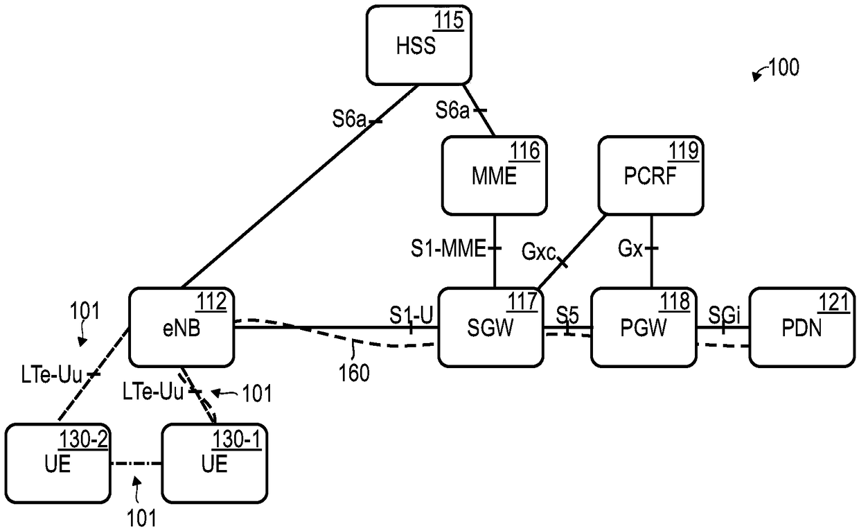
technical field [0001] Various embodiments relate to transmitting pilot signals over a radio link of a cellular network and to corresponding apparatus. Background technique [0002] Pilot signals (also sometimes referred to as reference signals) are commonly used to determine the state of channels implemented on radio links of cellular networks (channel sensing). Channel sensing may include channel estimation and channel measurement. In the reference implementation, pilot signals are transmitted repeatedly in order to account for the time dependence of the channel state, eg due to time-varying multipath effects or Doppler spread. A pilot signal is transmitted with well-defined transmission parameters such as amplitude and phase. From the received pilot signals and based on the knowledge of the transmission parameters, it is then possible to infer the properties of the radio link between the transmitter and the receiver, and to draw conclusions about the corresponding state...

Claims


Application Information

Patent Timeline
Patent Type & Authority Applications(China)
IPC IPC(8): H04L5/00
CPCH04L5/0048H04L5/0053H04W76/15H04W64/006H04W4/023H04B7/0413H04W72/0473
Inventor R·荣B·帕利延多布·拉尔森应志农E·本特松
Owner SONY CORP
Learn More