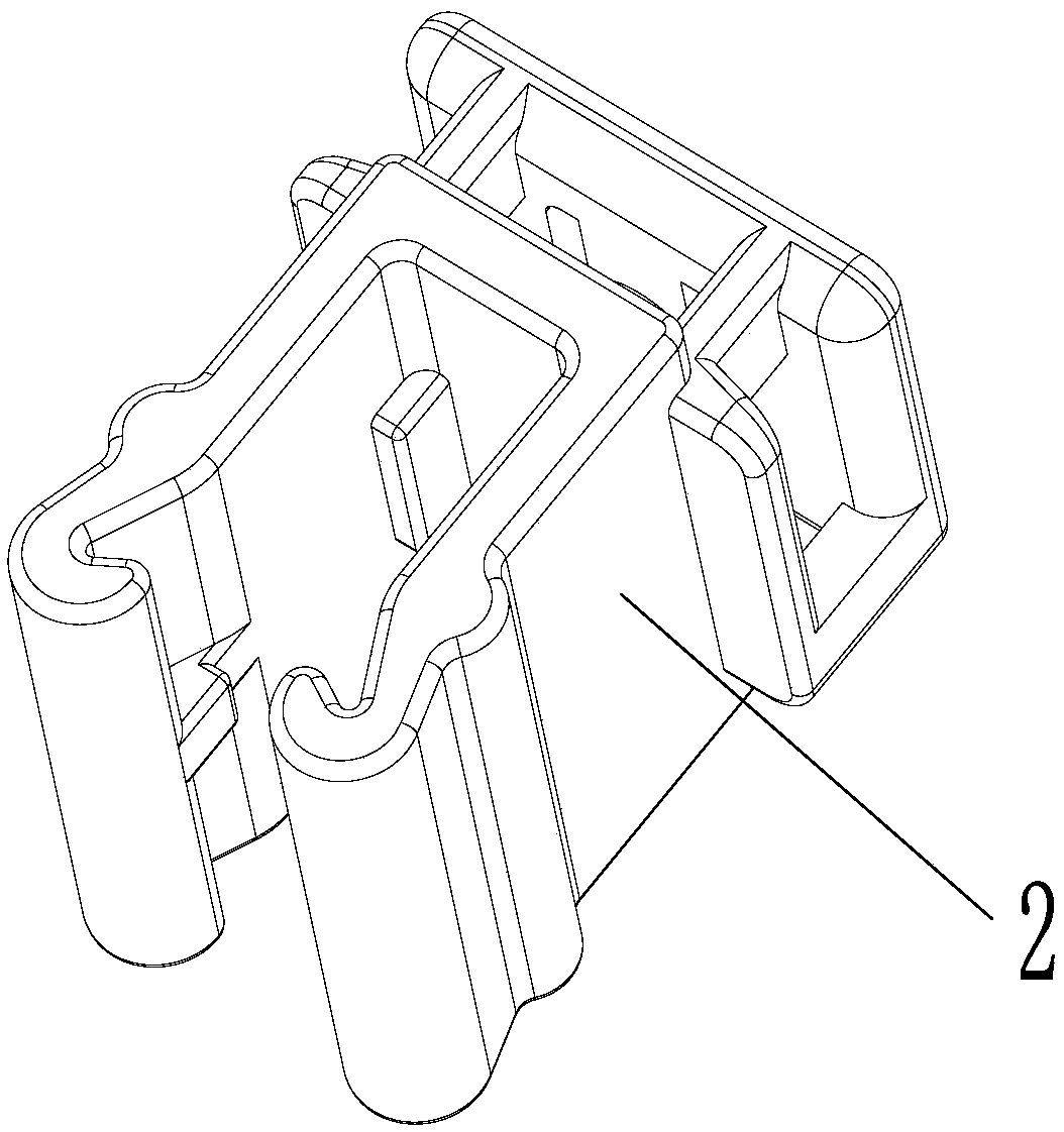
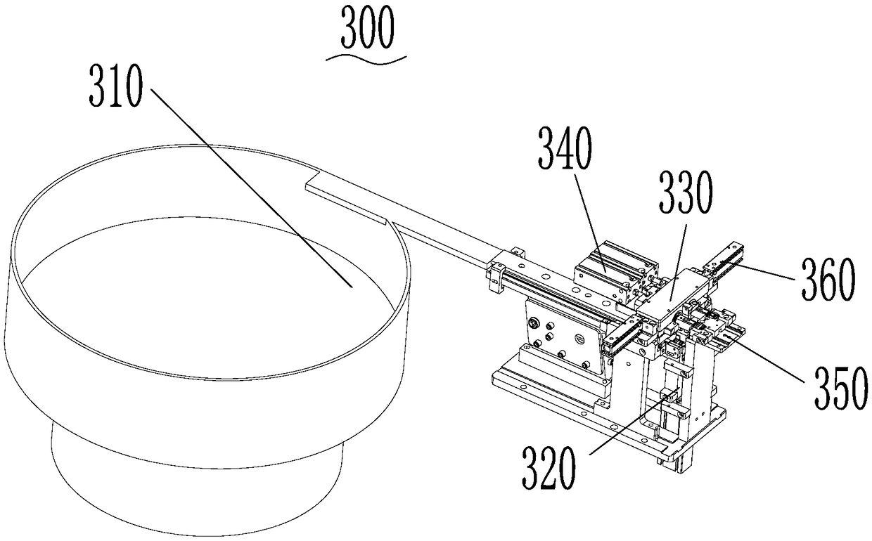
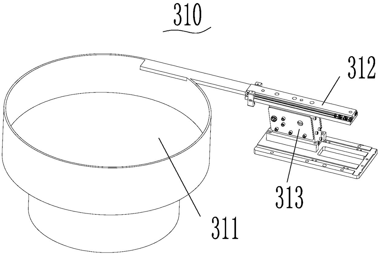
Material end feeding mechanism

A material head and component technology, applied in the field of cable ties and material head assembly, can solve the problems of inability to effectively meet the production requirements of industrial automation of enterprises, high labor intensity of workers, and high production costs, and achieve easy automatic assembly, simple structure, and high production cost. The effect of low production cost

Pending Publication Date: 2018-12-25
NINGBO SHILAM AUTO PARTS CO LTD
View PDF0 Cites 4 Cited by
  • Summary
  • Abstract
  • Description
  • Claims
  • Application Information

AI Technical Summary

Problems solved by technology

[0003] At present, the plug-in assembly of the cable tie and the material head is done manually. Since the cable tie and the material head are usually irregular in structure, this makes workers need to Use the human eye to distinguish the front and back of the cable tie and the material head, and then plug and assemble the corresponding ones. This not only has low assembly efficiency, but also has high labor intensity for workers, and the corresponding high production cost cannot effectively meet the needs of enterprises. Automated Production Requirements

Method used


Image

  • Material end feeding mechanism
  • Material end feeding mechanism
  • Material end feeding mechanism

Examples


Embodiment Construction

[0027] The following will clearly and completely describe the technical solutions in the embodiments of the present invention with reference to the accompanying drawings in the embodiments of the present invention. Obviously, the described embodiments are only some, not all, embodiments of the present invention. Based on the embodiments of the present invention, all other embodiments obtained by persons of ordinary skill in the art without making creative efforts belong to the protection scope of the present invention.

[0028] It should be noted that the upper jacking cylinder, the first jacking cylinder, the second jacking cylinder, and the rotary driving cylinder all refer to cylinders, and the above distinctions are only made for the convenience of understanding and description.

[0029] Unless otherwise defined, all technical and scientific terms used herein have the same meaning as commonly understood by one of ordinary skill in the technical field of the invention. The ...


PUM


Abstract

The invention discloses a material end feeding mechanism which comprises a material end track, a material end transferring component, a material end clamp, a material end push and jacking component and a material end jig, wherein the material end transferring component is connected with the material end track and is used for transferring a material end on the material end track to the positions ofthe material end clamp and the material end jig; the material end push and jacking component is capable of pushing and jacking the material end clamp to enable the material end clamp to clamp the material end on the material end transferring component and is used for moving the material end clamped by the material end clamp to the material end jig. The material end feeding mechanism is simple instructure and convenient to operate and control; due to reasonable structure arrangement, a function that material ends are automatically fed by using the material end feeding mechanism can be achieved, and convenience can be brought to later automatic assembling of ribbons and material ends.

Description

technical field [0001] The invention belongs to the technical field related to the assembly of cable ties and material heads, and in particular relates to a material head feeding mechanism for realizing automatic feeding of material ends. Background technique [0002] It can be understood that in the production process of automobiles, wire harnesses are often required to be bundled. The wire harnesses generally include cable ties and the material heads that match the cable ties. According to the needs of automobile production, it is usually necessary to insert the cable ties into Connect to the material head, and finally get the corresponding wire harness to provide to the customer. [0003] At present, the plug-in assembly of the cable tie and the material head is done manually. Since the cable tie and the material head are usually of irregular structure, this makes workers need to Use the human eye to distinguish the front and back of the cable tie and the material head, ...

Claims


Application Information

Patent Timeline
Patent Type & Authority Applications(China)
IPC IPC(8): B23P19/00
CPCB23P19/001B23P19/007
Inventor 沈卓峰周金体胡勇周敏
Owner NINGBO SHILAM AUTO PARTS CO LTD
Why Eureka
Try Eureka