
ratchet wrench

A technology of ratchet wrench and ratchet, which is applied in the field of wrenches, and can solve problems such as the loss of function of the ratchet wrench, the inability of the ratchet 12 to be effectively engaged, and the inability to be used to turn screws or nuts, etc., to achieve the effect of increasing the service life

Active Publication Date: 2021-01-22
豪越股份有限公司
View PDF7 Cites 0 Cited by
  • Summary
  • Abstract
  • Description
  • Claims
  • Application Information

AI Technical Summary

Problems solved by technology

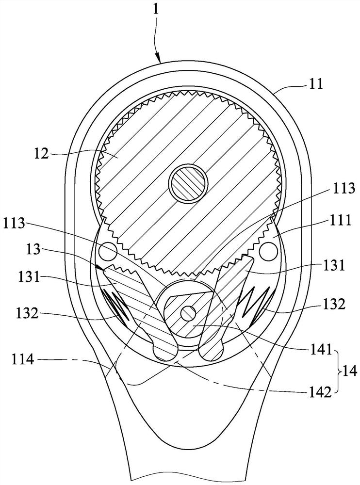
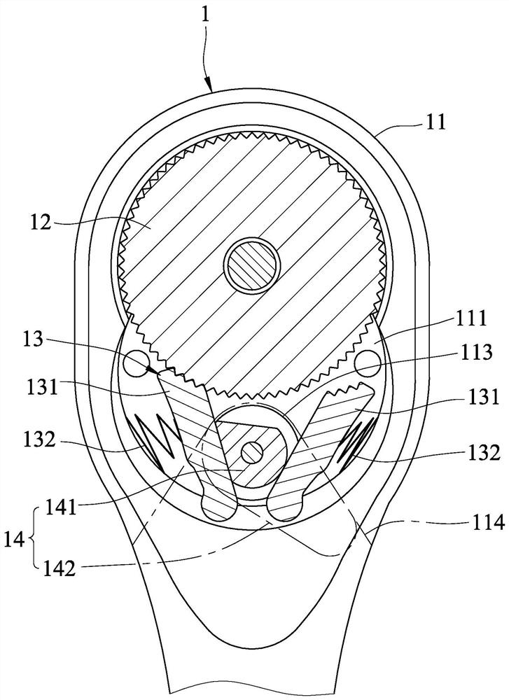
[0008] refer to Figure 5 and Image 6 When the toggle switch 142 crosses the range of the recessed area 112, it will drive the cam block 141 to rotate out of a predetermined range, so that the locking blocks 131 are all pushed against the ratchet 12, and the ratchet 12 Therefore, it loses the characteristic of only rotating in one direction, and cannot be used to turn screws or nuts, and the ratchet wrench 1 then loses its function
Therefore, after the ratchet wrench 1 is old and worn, the ratchet 12 cannot be effectively engaged when the steering is often switched.

Method used


Image

  • ratchet wrench
  • ratchet wrench
  • ratchet wrench

Examples


Embodiment Construction

[0046] Before the present invention is described in detail, it should be noted that in the following description, similar components are denoted by the same numerals. Wherein, in order to clearly describe the orientation or direction, the orientation or direction mentioned below refers to the orientation of the referenced drawing, and when referring to the right side, it refers to the right side of the referenced drawing.

[0047] refer to Figure 7 , Figure 8 and Figure 9 , a first embodiment of the ratchet wrench of the present invention includes: a body 2 , a ratchet 3 , a driving member 4 , a locking unit 5 , and a switching unit 6 .

[0048] The body 2 includes a head 21 and a handle 22 . The head 21 has a container 211 and a pivot hole 212 communicating with the outside and the container 211 . The handle 22 extends outward from the head 21 and can be held by a user.

[0049] The ratchet 3 is pivotably disposed in the slot 211 of the body 2 and includes a ratchet p...


PUM


Abstract

A ratchet wrench comprises a body, a ratchet, two clamping-pulling blocks and a switching unit. The body comprises a head part with an accommodating groove, the ratchet is arranged in the accommodating groove in a pivotal mode, and the clamping-pulling block is arranged in the accommodating groove in a pivoted mode. The switching unit comprises a switching piece, a sliding groove and a stopping block. The switching piece can be operated to abut against the clamping-pulling blocks in a pushing mode, so that the clamping-pulling blocks are alternatively engaged with the ratchet. The sliding groove is formed in one of the head part and the switching piece, and the stopping block is arranged at the other one of the head part and the switching piece and extends into the sliding groove in a protruding mode. The sliding groove and the stopping block can limit the rotating range of the switching piece, excessive rotation is avoided, and thus the ratchet can be effectively engaged; and the stopping block is accommodated in the sliding groove and is not liable to be abraded, and thus the service life of the ratchet wrench is prolonged.

Description

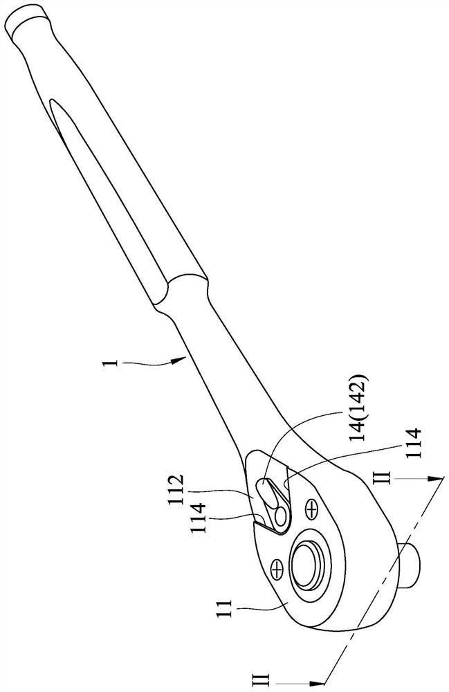
technical field [0001] The invention relates to a wrench, in particular to a ratchet wrench. Background technique [0002] refer to figure 1 , figure 2 and image 3 , a conventional ratchet wrench 1 includes a head 11 , a ratchet 12 , a locking unit 13 , and a switch 14 . The head 11 includes a cavity 111 , a recessed area 112 with two blocking surfaces 114 , and a pivot hole 113 disposed between the blocking surfaces 114 . The ratchet 12 is pivotally disposed in the slot 111 . The engaging unit 13 includes two engaging blocks 131 pivotally disposed in the receiving slot 111 , and two elastic members 132 . Each elastic member 132 abuts between the respective engaging block 131 and the inner wall of the receiving slot 111 . The switching member 14 includes a cam block 141 pivoted through the pivot hole 113 and located between the locking blocks 131 , and a toggle switch 142 formed at the end of the cam block 141 . The toggle switch 142 can be operated to rotate the ca...

Claims


Application Information

Patent Timeline
Patent Type & Authority Patents(China)
IPC IPC(8): B25B13/46
CPCB25B13/468
Inventor 赖盈良
Owner 豪越股份有限公司
Learn More