Spiral stabilizing mechanism suitable for transformer and implementation method thereof

A transformer and stable technology, applied in the field of transformers, can solve problems such as high limitations, time-wasting, and inability to adjust the limit, and achieve the effect of convenient use, flexible operation, and convenient height adjustment

Inactive Publication Date: 2021-04-06
无锡市惠利特种电源有限公司
View PDF0 Cites 0 Cited by
  • Summary
  • Abstract
  • Description
  • Claims
  • Application Information

AI Technical Summary

Problems solved by technology

[0003] The existing transformer stabilizing structure cannot adjust the limit according to the size and specification of the transformer. In use, the limit fixture of the specified size must be used to limit the transformer of the specified size, resulting in high limitations in use and limited replacement. Fixtures waste more time

Method used


Image

  • Spiral stabilizing mechanism suitable for transformer and implementation method thereof
  • Spiral stabilizing mechanism suitable for transformer and implementation method thereof
  • Spiral stabilizing mechanism suitable for transformer and implementation method thereof

Examples


Embodiment 1

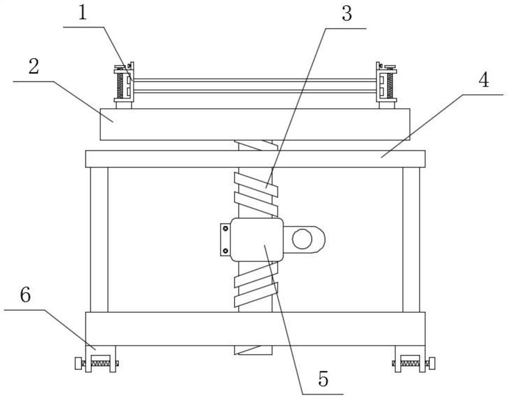
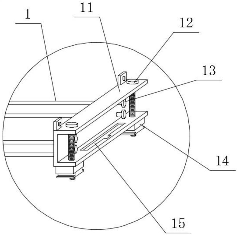
[0026] Such as Figure 1-2 As shown, a spiral stabilization mechanism suitable for transformers includes a frame 4, the bottom end surface of the frame 4 is fixedly connected with a bottom clip 6, and the inner surface of the frame 4 is movably connected with a screw rod 3 through a helical thread, and the screw rod 3 The top end surface is connected with the long plate 2 through the shaft rotation, and the top end surface of the long plate 2 is slidably connected with the limit clamp 1 through the chute. The limit clamp 1 includes a clamp body 11, and the top end surface of the clamp body 11 is movably connected with a long rod through a thread. 13, and the right end face of the clip body 11 is movably connected with a fixed screw 12, the inner side of the right end face of the clip body 11 is provided with a groove 15, and the bottom end face of the clip body 11 is fixedly connected with a slider 14.

[0027] When in use, the transformer that needs to be limited can be place...

Embodiment 2

[0029] Such as Figure 1-2 As shown, a spiral stabilization mechanism suitable for transformers includes a frame 4, the bottom end surface of the frame 4 is fixedly connected with a bottom clip 6, and the inner surface of the frame 4 is movably connected with a screw rod 3 through a helical thread, and the screw rod 3 The top end surface is connected with the long plate 2 through the shaft rotation, and the top end surface of the long plate 2 is slidably connected with the limit clamp 1 through the chute. The limit clamp 1 includes a clamp body 11, and the top end surface of the clamp body 11 is movably connected with a long rod through a thread. 13, and the right end face of the clip body 11 is movably connected with a fixed screw 12, the inner side of the right end face of the clip body 11 is provided with a groove 15, and the bottom end face of the clip body 11 is fixedly connected with a slider 14.

[0030] The inner side of the right end face of the limit clip 1 is provid...

Embodiment 3

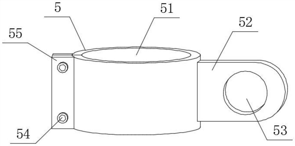
[0032] Such as Figure 1-3 As shown, a spiral stabilization mechanism suitable for transformers includes a frame 4, the bottom end surface of the frame 4 is fixedly connected with a bottom clip 6, and the inner surface of the frame 4 is movably connected with a screw rod 3 through a helical thread, and the screw rod 3 The top end surface is connected with the long plate 2 through the shaft rotation, and the top end surface of the long plate 2 is slidably connected with the limit clamp 1 through the chute. The limit clamp 1 includes a clamp body 11, and the top end surface of the clamp body 11 is movably connected with a long rod through a thread. 13, and the right end face of the clip body 11 is movably connected with a fixed screw rod 12, the inside of the right end face of the clip body 11 is provided with a groove 15, and the bottom end face of the clip body 11 is fixedly connected with a slider 14, and the connecting ring 5 includes There is a ring 51, the outer surface of...


PUM


Abstract

The invention provides a spiral stabilizing mechanism suitable for transformer and an implementation method thereof. The spiral stabilizing mechanism suitable for the transformer comprises a frame, wherein a bottom clamp is fixedly connected to the end face of the bottom end of the frame, a spiral rod is movably connected to the inner surface of the frame through threads, and a long plate is rotatably connected to the end face of the top end of the spiral rod through a shaft; an end face of a top end of the long plate is slidably connected with a limiting clamp through a sliding groove, the limiting clamp comprises a clamp body, an end face of the top end of the clamp body is movably connected with a long rod through threads, and the end face of the right end of the clamp body is movably connected with a fixing screw rod in an inserted mode. The transformer fixing device comprises the limiting clamp, the limiting clamp can adjust transformers of different sizes through horizontal movement and fixed-point fixing in the using process, the overall using flexibility is greatly improved, dependence on an external clamp is effectively reduced, using is more convenient and faster, and operation is more flexible.

Description

technical field [0001] The invention relates to the field of transformers, in particular to a spiral stabilization mechanism suitable for transformers and an implementation method thereof. Background technique [0002] Transformer is a device that uses the principle of electromagnetic induction to change AC voltage. The main components are primary coil, secondary coil and iron core. The main functions are: voltage conversion, current conversion, impedance conversion, isolation, voltage stabilization, etc. Different stabilizing mechanisms can be selected according to different transformer models during use. [0003] The existing transformer stabilizing structure cannot adjust the limit according to the size and specification of the transformer. In use, the limit fixture of the specified size must be used to limit the transformer of the specified size, resulting in high limitations in use and limited replacement. Fixtures waste a lot of time. Contents of the invention [0...

Claims


Application Information

Patent Timeline
Patent Type & Authority Applications(China)
IPC IPC(8): H01F27/02H01F27/06
CPCH01F27/02H01F27/06
Inventor 倪晓伟
Owner 无锡市惠利特种电源有限公司
Why Eureka
Try Eureka