Control device of efficient binding machine

A control device and binding machine technology, applied in binding and other directions, can solve problems such as insufficient aesthetics and poor punching quality

Inactive Publication Date: 2018-12-25
童良英
View PDF0 Cites 4 Cited by
  • Summary
  • Abstract
  • Description
  • Claims
  • Application Information

AI Technical Summary

Problems solved by technology

[0002] With the development of science and technology and the progress of society, the country has been promoting the development of high technology. In the field of office supplies, there has always been a relatively difficult technical problem, that is, in the process of paper binding, there are f

Method used


Image

  • Control device of efficient binding machine
  • Control device of efficient binding machine

Examples


Embodiment Construction

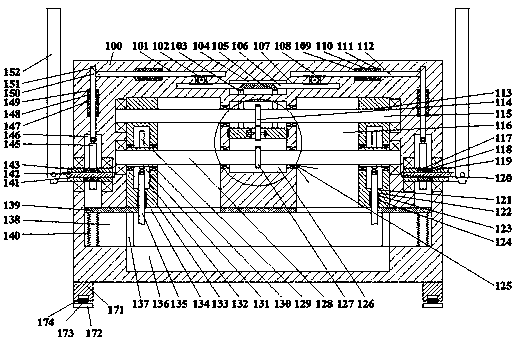
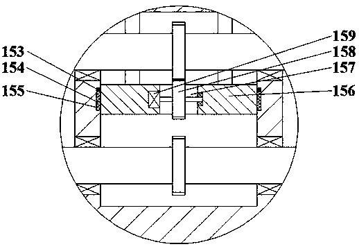
[0016] Such as Figure 1-Figure 2 As shown, the control device of the high-efficiency binding machine of the present invention includes a body 100, a first cavity 138 disposed in the body 100, and a second cavity 126 disposed in the body 100, the The top wall of the first cavity 138 is left and right symmetrically provided with the third cavity 116 with the opening downward. The first sliding block 139 can be slid up and down in the first cavity 138 . A through hole 134 corresponding to the third cavity 116 is symmetrically arranged left and right, and a second sliding block 133 is slidably arranged in the third cavity 116, and a left and right through hole is arranged in the second sliding block 133. The first threaded hole 113, the first threaded hole 113 is internally threaded and connected with the first threaded rod 115 passing through the second cavity 126, and the left and right sides of the first threaded rod 115 are rotated and arranged on the third In the end wall o...


PUM


Abstract

The invention discloses a control device of an efficient binding machine. The control device comprises a machine body, a first cavity and a second cavity, wherein the first cavity and the second cavity are formed inside the machine body; third cavities which are opened downwards are symmetrically formed left and right in the top wall of the first cavity; a first sliding block is arranged inside the first cavity in an up and down sliding manner; through holes corresponding to the third cavities are symmetrically formed left and right inside the first sliding block; second sliding blocks are arranged inside the third cavities in a sliding manner; first threaded holes are formed inside the second sliding blocks in a left and right through manner. The control device disclosed by the inventionis simple in structure and convenient to operate, a paper limiting plate is driven by a same power source to move to clamp paper and drive a paper cutter rod to move up and down, and meanwhile, switching of the functions is achieved while the paper is compressed; the paper is positioned by using the paper limiting plate, meanwhile, the paper is compressed and positioned through paper pressing blocks, then the paper can be bound tidily, the paper binding quality and attractiveness can be improved, different procedures are mutually matched without influence, and the practicability of the deviceis improved.

Description

technical field [0001] The invention relates to the field of office supplies, in particular to a control device for a high-efficiency binding machine. Background technique [0002] With the development of science and technology and the progress of society, the country has been promoting the development of high technology. In the field of office supplies, there has always been a relatively difficult technical problem, that is, in the process of paper binding, there are few devices that can not only limit the width of the paper but also Press the paper, and the existing equipment uses manual punching, which often results in poor punching quality and insufficient aesthetics due to uneven force control. Therefore, a device is urgently needed to solve such problems. Contents of the invention [0003] The technical problem to be solved by the present invention is to provide a control device for a high-efficiency binding machine, which can solve the above-mentioned problems in th...

Claims


Application Information

Patent Timeline
IPC IPC(8): B42B5/02
CPCB42B5/02
Inventor 童良英
Owner 童良英
Why Eureka
Try Eureka