Steel bar binding tool and method

A technology for binding steel bars and tools, which is applied in the processing of building materials, construction, building structure, etc., and can solve the problems of expensive, difficult binding of steel bars, and heavy weight.

Active Publication Date: 2021-07-30
四川国恒建筑设计有限公司
View PDF14 Cites 2 Cited by
  • Summary
  • Abstract
  • Description
  • Claims
  • Application Information

AI Technical Summary

Problems solved by technology

When binding the existing steel bars, it is usually necessary to use a steel bar hook or an electric steel bar binding device for binding. However, when using a steel bar hook, the operator needs to hold the binding wire in one hand and insert the binding wire under the binding node. Pull out the binding wire from the other side, operate the hook with one hand, hook the hook, and bind wi

Method used


Image

  • Steel bar binding tool and method
  • Steel bar binding tool and method
  • Steel bar binding tool and method

Examples


Embodiment

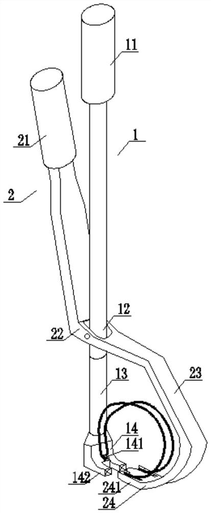
[0048] Such as figure 1 As shown, a steel bar binding tool, comprising:

[0049] The main arm 1, the main arm 1 includes a first gripping end 11, a first hinge portion 12, a first frame portion 13 and a first clamping end 14 connected in sequence;

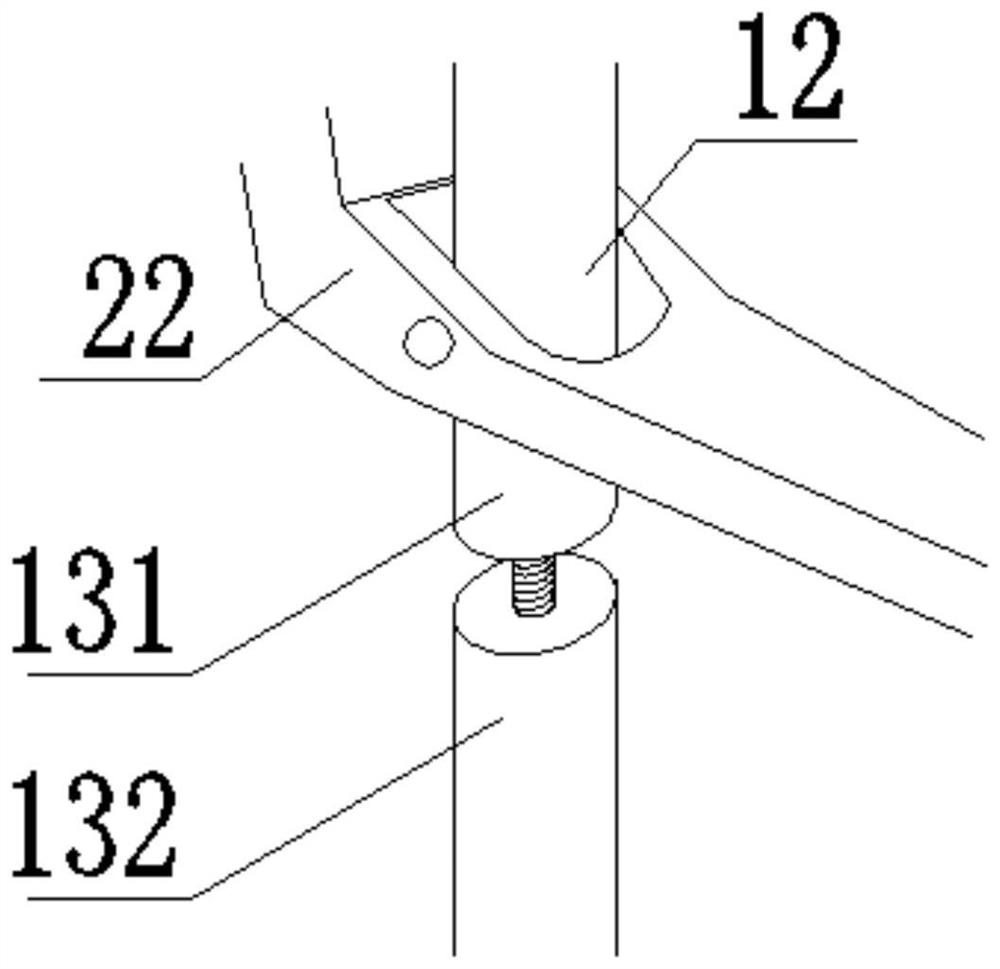
[0050] Among them, such as figure 2 As shown, the first frame part 13 includes an upper frame part 131 close to the first hinge part 12 and a lower frame part 132 close to the first clamping end 14, the upper frame part 131 One end close to the lower frame part 132 is provided with a threaded hole, and one end of the lower frame part 132 close to the upper frame part 131 is provided with a threaded rod adapted to the threaded hole. The rod is connected to the threaded hole, and the lower frame part 132 rotates around the axis of the threaded rod as the upper frame part 131 moves away;

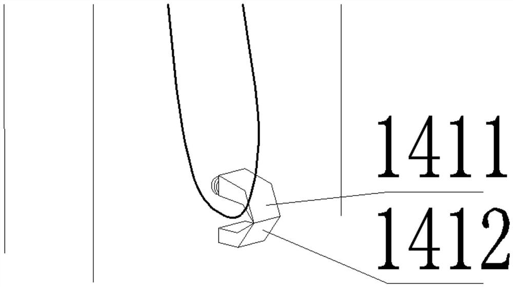
[0051] A pre-clamping part 141, the pre-clamping part 141 is arranged on the first clamping end 14, and is used to clamp one end of the binding...


PUM


Abstract

The invention discloses a steel bar binding tool and method, relates to the technical field of building construction, and can go deep into some narrow parts to preliminarily bind steel bars at the narrow parts. The tool comprises a main arm and an auxiliary arm which are hinged to each other, wherein the main arm is provided with a first frame body part and a first clamping end, the first frame body part comprises an upper frame body part and a lower frame body part which are in threaded connection, the first clamping end is provided with a pre-clamping part and a rear clamping part, the auxiliary arm is provided with a second frame body part and a second clamping end, and a front clamping part is arranged on the second clamping part. Through cooperation of the main arm and the auxiliary arm, surrounding and binding operation of steel bars can be completed without other tools, operation is easy and fast, the space needed by the operation is small, the tool can enter some complex positions for binding conveniently, and the binding quality of the steel bars at complex positions is improved.

Description

technical field [0001] The invention relates to the technical field of building construction, in particular to a steel bar binding tool and method. Background technique [0002] At present, in the process of building construction, a large amount of steel bars are usually used, which brings about heavy steel bar binding operations. When binding the existing steel bars, it is usually necessary to use a steel bar hook or an electric steel bar binding device for binding. However, when using a steel bar hook, the operator needs to hold the binding wire in one hand and insert the binding wire under the binding node. Pull out the binding wire from the other side, operate the hook with one hand, hook the hook, and bind with both hands, which is very inconvenient; the electric steel bar binding device is a structure similar to a gun body, but it is relatively large in size and heavy in weight. The price is relatively expensive, and when performing operations, only some binding nodes...

Claims


Application Information

Patent Timeline
IPC IPC(8): E04G21/12
CPCE04G21/123
Inventor 曹历
Owner 四川国恒建筑设计有限公司
Why Eureka
Try Eureka