Semi-automatic manufacturing method of cast-in-place pile reinforcement cage

A kind of cage semi-automatic, manufacturing method technology, applied in sheet pile walls, structural elements, building components and other directions, can solve the problems of uncontrollable construction progress, slow steel bar binding, many hidden dangers after construction, etc., to achieve good promotion and application value, reduce Investment in equipment costs and the effect of improving binding efficiency

Inactive Publication Date: 2021-02-05
中国建筑土木建设有限公司
View PDF4 Cites 2 Cited by
  • Summary
  • Abstract
  • Description
  • Claims
  • Application Information

AI Technical Summary

Problems solved by technology

[0004] The purpose of the present invention is to provide a semi-automatic manufacturing method for cast-in-place pile reinforcement cages, which can solve the technical problems of slow binding speed of reinforcement, low quality of finished products, uncontrollable construction progress, poor line quality, and many hidden dangers after construction

Method used


Image

  • Semi-automatic manufacturing method of cast-in-place pile reinforcement cage
  • Semi-automatic manufacturing method of cast-in-place pile reinforcement cage
  • Semi-automatic manufacturing method of cast-in-place pile reinforcement cage

Examples


Embodiment

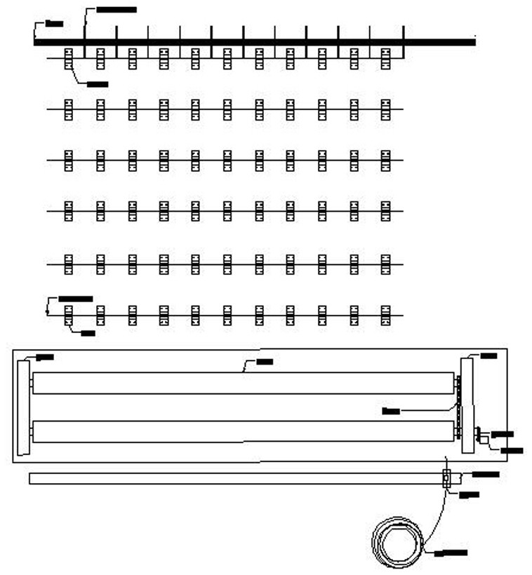
[0038] Such as Figure 1-7 As shown, the invention provides a semi-automatic manufacturing method for cast-in-place pile reinforcement cage, comprising the steps of:

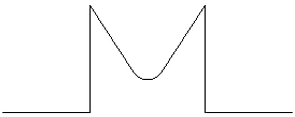
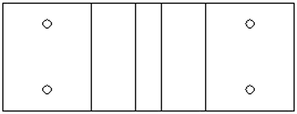
[0039] Step 1, install the limit card 1 of the main reinforcement of the reinforcement cage on the hardened site; the longitudinal spacing is 2m, and the horizontal spacing is set according to the spacing of the main reinforcement of the reinforcement cage d=2πr / n-1; r is the radius of the reinforcement cage, and n is the number of the main reinforcement of the reinforcement cage . The limit card 1 includes two L-shaped connecting parts with opposite openings and a V-shaped main rib receiving groove arranged between the L-shaped connecting parts; the L-shaped connecting part includes a vertical plate and a horizontal plate arranged on the ground, and the horizontal plate There are round holes for passing bolts on the top, and the two top ends of the V-shaped main reinforcement receiving groove are respectively ...


PUM


Abstract

The invention discloses a semi-automatic manufacturing method of a cast-in-place pile reinforcement cage. The semi-automatic manufacturing method comprises the following steps that 1, reinforcement cage main reinforcement limiting clamps are installed on a hardened site; 2, the axes of machined reinforcement cage reinforcing rings are connected in series, the reinforcing rings connected in seriesare welded to a first reinforcing steel bar, the reinforcing rings are rolled to a second main reinforcing steel bar to be welded, and so on, welding is conducted, and binding of main reinforcing steel bars is completed; and 3, two rolling shafts with the interval of 30 cm are arranged at the last main reinforcing steel bar, one end of each rolling shaft is connected with a motor and rotates alongwith the motor, and one end of each stirrup penetrates through a movable sliding block to be welded to the reinforcement cage. Manufacturing is easy, operation is convenient, and the binding efficiency and quality of stirrups can be improved through the sliding blocks and the rolling shafts. The main reinforcing steel bars can be distributed on a bracket according to a fixed interval, the reinforcement cage reinforcing rings are placed on the first main reinforcing steel bar and the second main reinforcing steel bar, meanwhile, the longitudinal interval of the reinforcement cage reinforcing rings is adjusted according to design requirements, and welding is conducted.

Description

technical field [0001] The invention relates to the technical field of steel cage production, in particular to a semi-automatic production method for cast-in-place pile steel cages. Background technique [0002] The main function of the reinforcement cage is the same as that of the vertical reinforcement of the column. It mainly plays a role in tensile strength. The compressive strength of concrete is high but the tensile strength is very low. It acts as a constraint on the concrete of the pile body so that it can bear a certain axial tension. During the construction of bridges, culverts or high-rise buildings, the foundation may be required to be piled according to requirements. The method is to use machine punching and water mill drilling, and the hole depth meets the design requirements, and then lower the reinforcement cage to the pile hole, and then insert the conduit for concrete pouring. [0003] During the construction of the reinforcement cage, the reinforcing ring...

Claims


Application Information

Patent Timeline
Patent Type & Authority Applications(China)
IPC IPC(8): B21F27/12B21F27/10E04C5/06E02D5/34
CPCB21F27/12B21F27/10E04C5/06E02D5/34
Inventor 徐林峰宋合财张力强胡志华高树青刘小南王靖靖刘文龙
Owner 中国建筑土木建设有限公司
Why Eureka
Try Eureka