

A transformer iron core automatic laminating production line
A technology for transformer cores and production lines, which is used in inductance/transformer/magnet manufacturing, electrical components, circuits, etc., can solve the problems of large labor costs, heavy workload, low production efficiency, etc., to ensure beautiful appearance and improve production efficiency. , the effect of reducing production costs
- Summary
- Abstract
- Description
- Claims
- Application Information
AI Technical Summary
Problems solved by technology
Method used
Image

Examples
Embodiment Construction
[0033] Below in conjunction with each accompanying drawing, the present invention is described in detail.
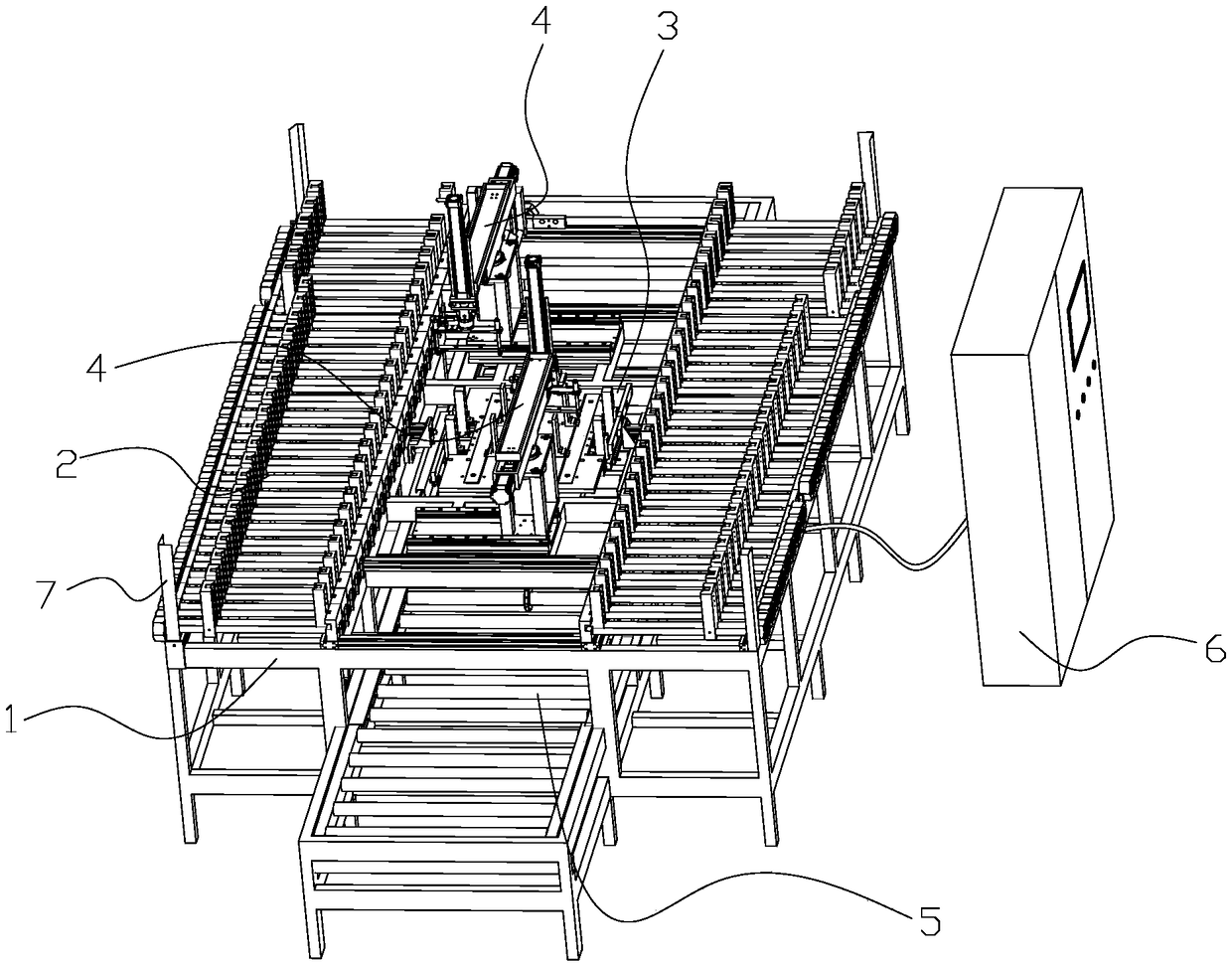
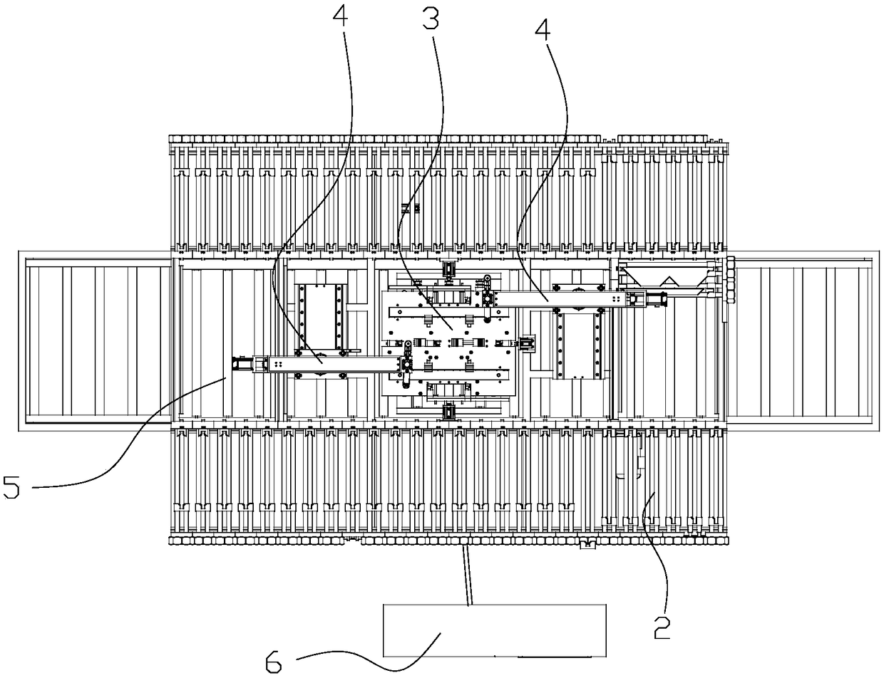
[0034] to combine figure 1 and figure 2 , the automatic lamination production line of the transformer iron core according to the present invention includes a support 1 , a silo 2 , a lamination platform 3 , a pick-and-place mechanism 4 , a transmission mechanism 5 and a control cabinet 6 . The silo 2 , the pick-and-place mechanism 4 and the transmission mechanism 5 are fixed on the support frame, and the lamination platform 3 is placed on the transmission mechanism 5 . A plurality of silos 2 are installed on the support 1, and each of the silos 2 is put into stacks of the same specification, and the pick-and-place mechanism 4 is used to grab the stacks in the silos 2 and place them On the lamination platform 3, the transfer mechanism 5 is used to send the lamination platform 3 to the lamination range of the pick-and-place mechanism 4 and send out the lamination platfo...
PUM
 Abstract
Description
Claims
Application Information