
Self-locking sliding block device applied to injection mold

A technology of injection mold and slider, which is applied in the field of self-locking slider device, can solve the problem of product reaction force formed by shovel foundation, reduce mold production cost, mold molding cycle and other issues

Pending Publication Date: 2018-12-28
YIHE PRECISION IND SUZHOU
View PDF0 Cites 0 Cited by
  • Summary
  • Abstract
  • Description
  • Claims
  • Application Information

AI Technical Summary

Problems solved by technology

[0003] In view of this, the present invention provides a self-locking slider device applied to injection molds that can effectively solve the problem of product reaction force formed by shovel base, reduce mold manufacturing costs and shorten mold molding cycle

Method used


Image

  • Self-locking sliding block device applied to injection mold
  • Self-locking sliding block device applied to injection mold

Examples


Embodiment 1

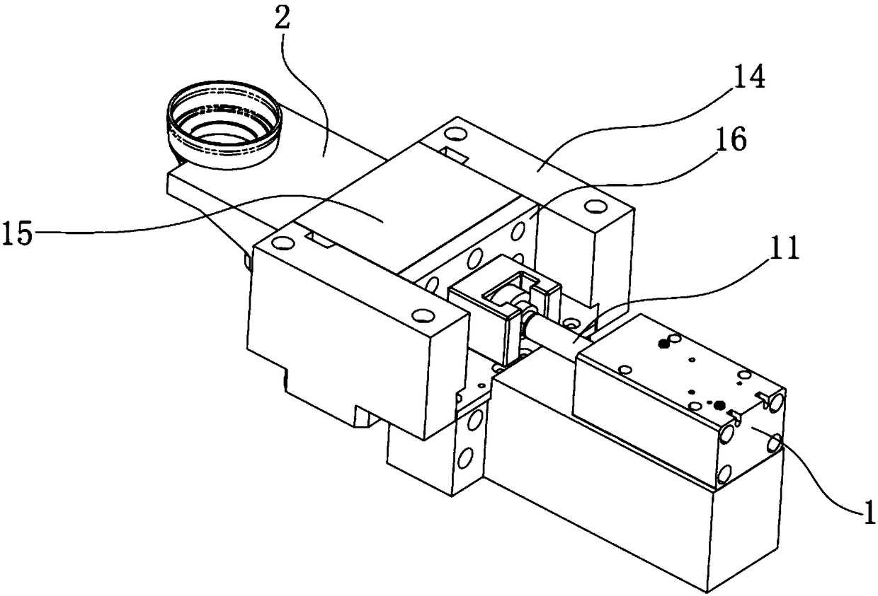
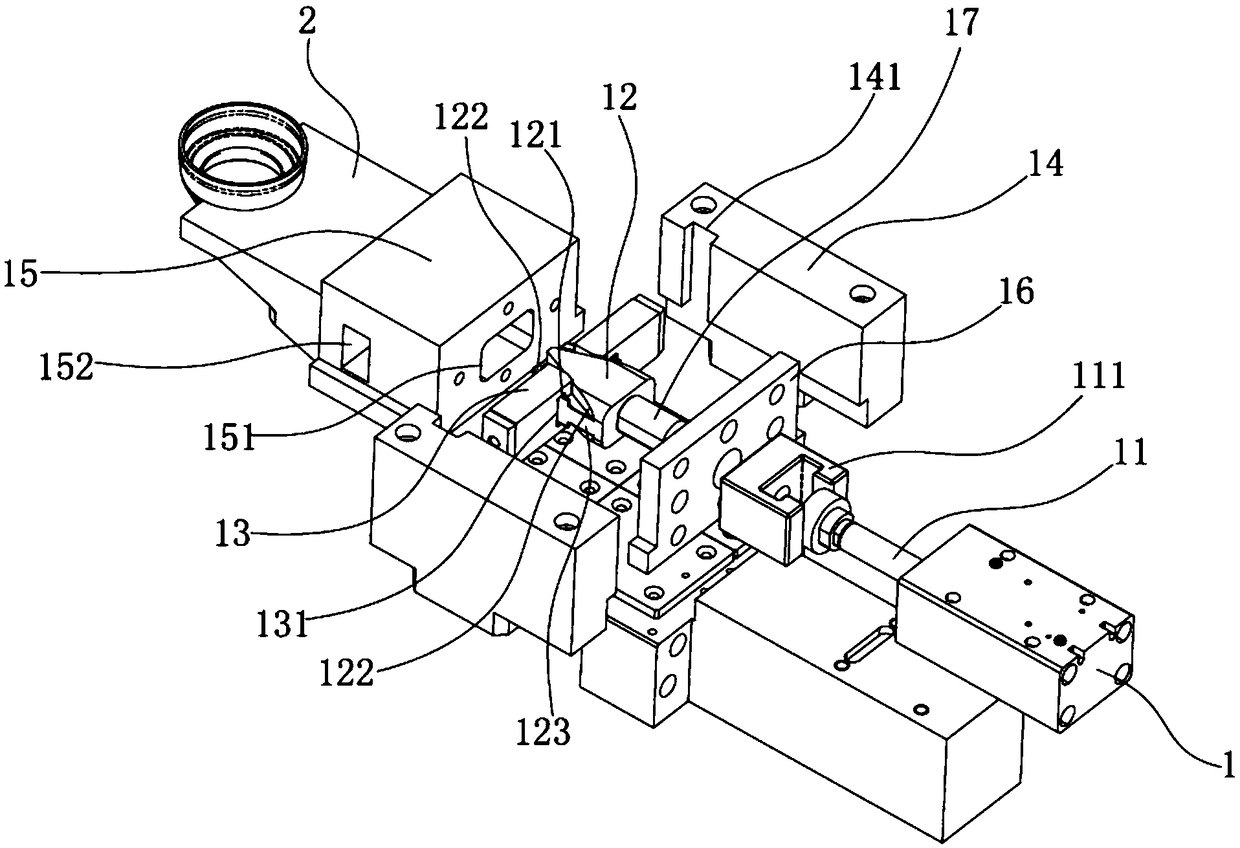
[0023] see Figure 1 to Figure 2 , the figure shows a self-locking slider device applied to injection molds provided by Embodiment 1 of the present invention, which includes a linear drive device 1, which may specifically be an oil cylinder, and the drive shaft 11 of the linear drive device 1 is fixedly connected to There is a latch dial 12, two paddles 121 are arranged on opposite sides of the latch dial 12 respectively, the paddles 121 are V-shaped paddles, which have an open end 122, and the latch 13 is set on the paddle 121, and the latch 13 is There is a preset first through hole 131, the plectrum 121 can be movably inserted into the first through hole 131 from its open end 122, and two pressing bars 14 are respectively arranged on the opposite sides of the latch shifting block 12, and the inside of the pressing bar 14 The side is provided with a self-locking groove 141, and the end of the latch 13 is self-lockingly matched with the self-locking groove 141, and the end of...

Embodiment 2

[0029] see Figure 1 to Figure 2 , the figure shows a self-locking slider device applied to injection molds provided by Embodiment 2 of the present invention. On the basis of the above embodiments, this embodiment further makes the following technical solutions as improvements: latch The end of shifting block 12 is connected with slide block 15, and slide block 15 is fixedly connected with product forming mold 2; There is hole body 151 for latch shift block 12 to enter on slide block 15, and hole body 151 is a blind hole. Through the setting of the above structure, the installation of the latch shifting block can be made more stable, and the stroke can be more precise.

Embodiment 3

[0031] see Figure 1 to Figure 2 , the figure shows a self-locking slider device applied to injection molds provided by Embodiment 3 of the present invention. This embodiment further makes the following technical solutions as improvements on the basis of the above embodiments: sliding The block 15 is a rectangular slider, and the opposite sides of the slider 15 are respectively provided with two second through holes 152, the second through holes 152 communicate with the hole body 151, the second through holes 152 are perpendicular to the hole body 151, and the latch 13 is in the second Move back and forth in the through hole 152 . Through the setting of the above structure, the installation of the bolt can be made more stable, and the stroke can be more precise.


PUM


Abstract

The invention provides a self-locking sliding block device applied to an injection mold. The self-locking sliding block device comprises a linear driving device, wherein a driving shaft of the lineardriving device is fixedly connected with a plug shifting block, the two opposite sides of the plug shifting block are respectively provided with two shifting pieces, the shifting pieces are V-shaped shifting pieces and are provided with opening ends, plugs sleeve the shifting pieces, preset first through holes are formed in the plugs, the shifting pieces are movably inserted into the first throughholes from the open ends of the shifting pieces, two pressing strips are arranged on the two opposite sides of the plug shifting block respectively, self-locking grooves are formed in the inner sidefaces of the pressing strips, the end parts of the plugs are matched with the self-locking grooves in a self-locking mode, and the end part of the plug shifting block is further connected with a product forming mold. Compared with the prior art, the problem that a product counter-acting force is formed by a shovel base can be effectively solved, and meanwhile, the manufacturing cost of the mold isreduced, and the forming period of the mold is shortened.

Description

technical field [0001] The invention relates to the field of injection molds, in particular to a self-locking slider device applied to injection molds. Background technique [0002] In the product molding operation of injection molds, some products require a slider mechanism to be demolded. However, because some slider mechanisms usually have a shovel base design, when they act on the product’s demoulding, they will form a reaction force during the injection molding of the product. The situation, thus affecting the demoulding efficiency. In addition, the structure of the shovel base is relatively complicated, and the manufacturing cost of the mold is relatively high, which will also result in a long molding cycle of the mold. Contents of the invention [0003] In view of this, the present invention provides a self-locking slider device applied to injection molds that can effectively solve the problem of product reaction force formed by shovel foundation, reduce mold manuf...

Claims


Application Information

Patent Timeline
Patent Type & Authority Applications(China)
IPC IPC(8): B29C45/33
CPCB29C45/33
Inventor 张敏
Owner YIHE PRECISION IND SUZHOU
Learn More