
Auxiliary drive device

一种辅助驱动、四轮驱动的技术,应用在动力装置、电动力装置、控制装置等方向,能够解决工作延迟时间变长、驾驶者或同乘者不愉快感、大振动或声音等问题,达到降低振动的效果

Active Publication Date: 2018-12-28
JTEKT CORP
View PDF10 Cites 1 Cited by
  • Summary
  • Abstract
  • Description
  • Claims
  • Application Information

AI Technical Summary

Problems solved by technology

However, in the structure described in Japanese Patent Application Laid-Open No. 2003-80962, it takes time until the electromagnetic clutch is connected and the ball cam mechanism is operated, and the multi-plate clutch is pressed by the thrust of the cam to generate friction between the clutch plates. The operation delay time from the switching of the wheel drive state until the auxiliary drive wheel is driven becomes longer
[0006] Therefore, the present inventors have considered the situation that the meshing clutch that transmits the driving force through the meshing of the meshing teeth is provided on the driving force transmission path of the motor, but when the meshing teeth are meshed, a large vibration or sound will be generated, which may be disturbing to the driver. discomfort to passengers or fellow passengers

Method used


Image

  • Auxiliary drive device
  • Auxiliary drive device
  • Auxiliary drive device

Examples


Embodiment Construction

[0023] Embodiments of the present invention will be described with reference to the drawings.

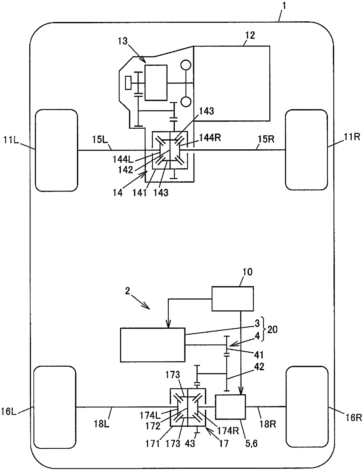
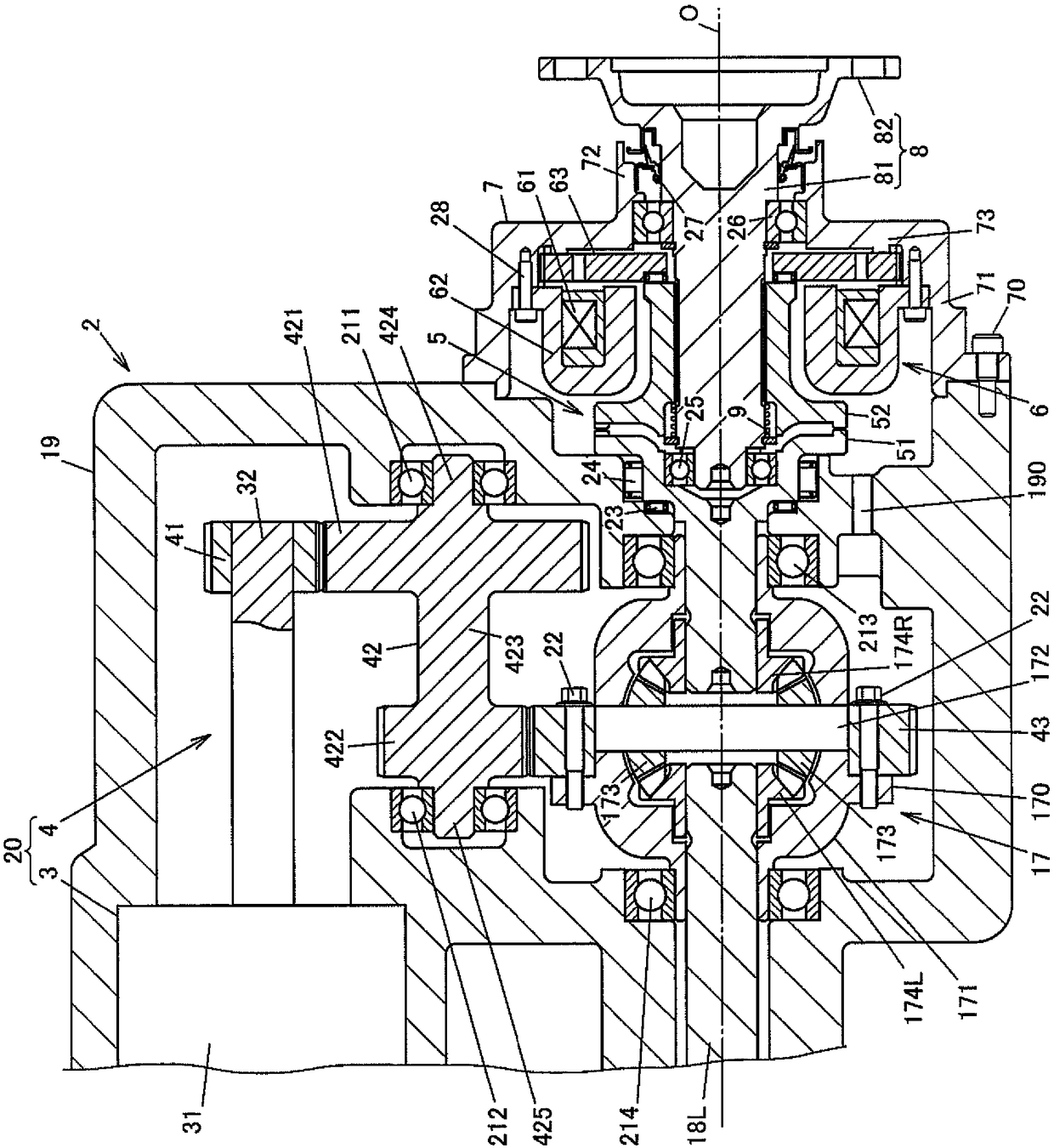
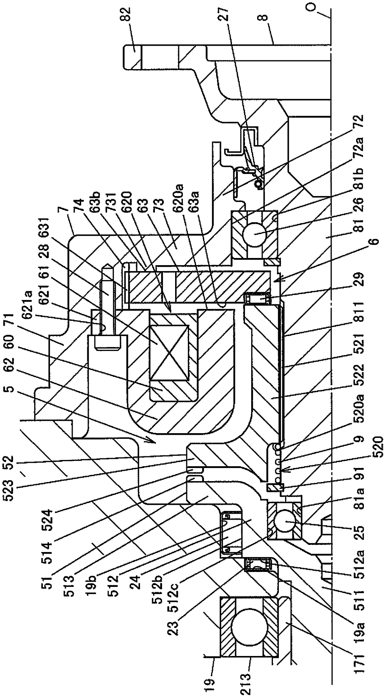
[0024] figure 1 It is a schematic diagram showing a configuration example of a four-wheel drive vehicle equipped with an auxiliary drive device according to an embodiment of the present invention. figure 2 It is a sectional view showing a structural example of the driving force transmission device. image 3 Indicates the main part of the driving force transmission device figure 2 A partial enlargement of the .

[0025] The left and right front wheels 11L, 11R of the four-wheel drive vehicle 1 are driven by an engine 12 serving as a main drive source, and the left and right rear wheels 16L, 16R are driven by an auxiliary drive device 2 having an electric motor 3 . In the present embodiment, the left and right front wheels 11L, 11R are main drive wheels, and the left and right rear wheels 16L, 16R are auxiliary drive wheels. In the following description, "left" and "right" refer...


PUM


Abstract

The invention provides an auxiliary drive device, and the auxiliary drive device (2) includes: a drive unit (20) that has an electric motor (3); a meshing clutch (5) that has a first meshing member (51) and a second meshing member (52); an actuator (6) that moves the second meshing member (52); and a control unit (10) that controls the electric motor (3) and the actuator (6). The actuator (6) moves the second meshing member (52) among a separation position, at which the second meshing member (52) is not meshed with the first meshing member (51), an abutment position, at which first meshing teeth and second meshing teeth possibly abut against each other, and a meshing position, at which the first meshing teeth and the second meshing teeth are meshed with each other. The control unit makes acurrent supplied to the electric motor when the second meshing member (52) is located between the abutment position and the meshing position smaller than a current required to maintain the rotationalspeed of the electric motor (3).

Description

technical field [0001] The present invention relates to auxiliary drives for vehicles. Background technique [0002] Conventional four-wheel drive vehicles have a configuration in which main drive wheels are driven by driving force of an engine shifted by a transmission, and auxiliary drive wheels are driven by an auxiliary drive device having an electric motor. For example, refer to Japanese Patent Application Laid-Open No. 2003-80962. [0003] In such a four-wheel drive vehicle, a clutch is provided on the drive force transmission path of the electric motor in the auxiliary drive device. When a large drive force is required in the low-to-middle speed range of the vehicle speed, the clutch is in a connected state so that the main drive wheels and the auxiliary drive wheels are equal to each other. Driven 4WD state. On the other hand, in the high-speed range, or when a large drive force is not required even though it is in the middle-low speed range, the motor stops and th...

Claims


Application Information

Patent Timeline
Patent Type & Authority Applications(China)
IPC IPC(8): B60K17/356
CPCB60K17/356F16D27/118F16D2011/008B60K17/354B60K1/00B60K2001/001B60K23/08B60K2023/0833B60K2023/0858B60K23/0808F16D23/02F16D11/14
Inventor 繁田良平须增宽
Owner JTEKT CORP
Features
  • Generate Ideas
  • Intellectual Property
  • Life Sciences
  • Materials
  • Tech Scout
  • Unparalleled Data Quality
  • Higher Quality Content
  • 60% Fewer Hallucinations
Learn More