A cross twin-rotor unmanned helicopter and a protection frame thereof
An unmanned helicopter and dual-rotor technology, applied in the field of helicopters, can solve problems such as the inability to cross the dual-rotor unmanned helicopter to land smoothly, and achieve the effects of not being prone to rollover, avoiding forward and rollover, and strong adaptability
Pending Publication Date: 2018-12-28
北京清航紫荆装备科技有限公司
View PDF0 Cites 0 Cited by
- Summary
- Abstract
- Description
- Claims
- Application Information
AI Technical Summary
Problems solved by technology
The protective frame of the traditional cross-rotor unmanned helicopter mostly adopts a skid structure. However, when the cross-rotor unmanned helicopter lands, especially when the cross-rotor unmanned helicopter is on a complex ground, the cross-rotor unmanned helicopter There is a risk of tilting the fuselage in all directions, and the skid-type protective frame can only prevent the cross-rotor unmanned helicopter from turning forward. When the center of gravity of the cross-rotor unmanned helicopter tilts sideways, the protective frame cannot Make the intersecting twin-rotor unmanned helicopter land smoothly
Method used
View moreImage
Smart ImageViewing Examples

Examples
Embodiment Construction
Login to View More PUM
 Abstract
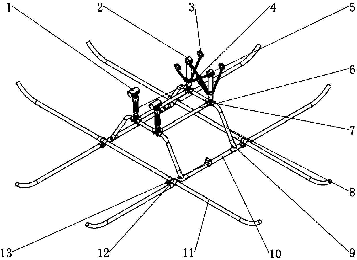
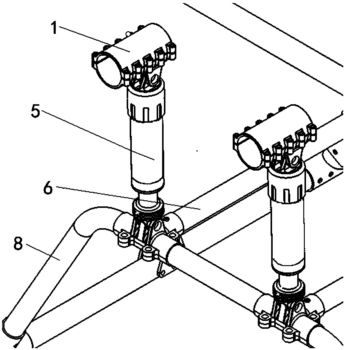
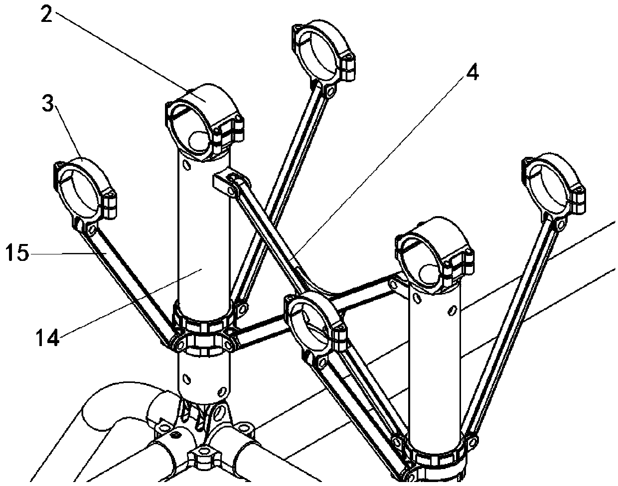
The invention discloses a protection frame of a cross twin-rotor unmanned helicopter, comprising a connecting frame for connecting with the fuselage of the cross twin-rotor unmanned helicopter and a protection beam fixedly connected with the connecting frame, wherein the protection beam comprises two longitudinal bars and two transverse bars, and the transverse bars and the longitudinal bars are arranged in a zigzag shape. The cross twin rotor unmanned helicopter provided by the present application adopts the longitudinal bar and the transverse bar distributed in the shape of a well, can avoidthe forward turning and the side turning of the cross twin rotor unmanned helicopter, has high protection performance for the cross twin rotor unmanned helicopter, and enables the cross twin rotor unmanned helicopter to land smoothly on the complex ground. The invention also discloses a cross double-rotor unmanned helicopter, which has strong adaptability to external environment and is difficultto roll over when landing.
Description
technical field The invention relates to the technical field of helicopters, more specifically, to a protective frame. In addition, the present invention also relates to an unmanned cross-rotor helicopter comprising the protective frame. Background technique The cross-rotor unmanned helicopter is prone to unstable landing due to the offset of the center of gravity when landing. In order to improve the stability of the cross-rotor unmanned helicopter when it lands, the cross-rotor unmanned helicopter is usually equipped with a protective frame. The protective frame of the traditional cross-rotor unmanned helicopter mostly adopts a skid structure. However, when the cross-rotor unmanned helicopter lands, especially when the cross-rotor unmanned helicopter is on a complex ground, the cross-rotor unmanned helicopter There is a risk of tilting the fuselage in all directions, and the skid-type protective frame can only prevent the cross-rotor unmanned helicopter from turning forw...
Claims
Login to View More Application Information
Patent Timeline
 IPC IPC(8): B64D45/06B64C27/08
CPCB64C27/08B64D45/06
Inventor 海日汗赵鹏博印明威包长春李京阳王贤宇
Owner 北京清航紫荆装备科技有限公司
Features
- R&D
- Intellectual Property
- Life Sciences
- Materials
- Tech Scout
- Unparalleled Data Quality
- Higher Quality Content
- 60% Fewer Hallucinations
Learn More Browse by: Latest US Patents, China's latest patents, Technical Efficacy Thesaurus, Application Domain, Technology Topic, Popular Technical Reports.
© 2025 PatSnap. All rights reserved.Legal|Privacy policy|Modern Slavery Act Transparency Statement|Sitemap|About US| Contact US: help@patsnap.com