
Airbag for knee protection

A knee and airbag technology, applied in the field of knee protection airbags, can solve the problems of increased manufacturing hours and costs

Inactive Publication Date: 2009-04-01
TOYODA GOSEI CO LTD
View PDF1 Cites 6 Cited by
  • Summary
  • Abstract
  • Description
  • Claims
  • Application Information

AI Technical Summary

Problems solved by technology

[0006] That is, in the existing knee protection airbag, because the upper and lower two-stage laces are provided, or the coated cloth with the coating is used as the base fabric for the airbag to manufacture the airbag, the manufacturing process of the airbag The cost increases, so it is desirable to reduce the number of straps and make the airbag from a woven fabric of uncoated cloth that is not provided with a coating

Method used


Image

  • Airbag for knee protection
  • Airbag for knee protection
  • Airbag for knee protection

Examples


Embodiment approach 1

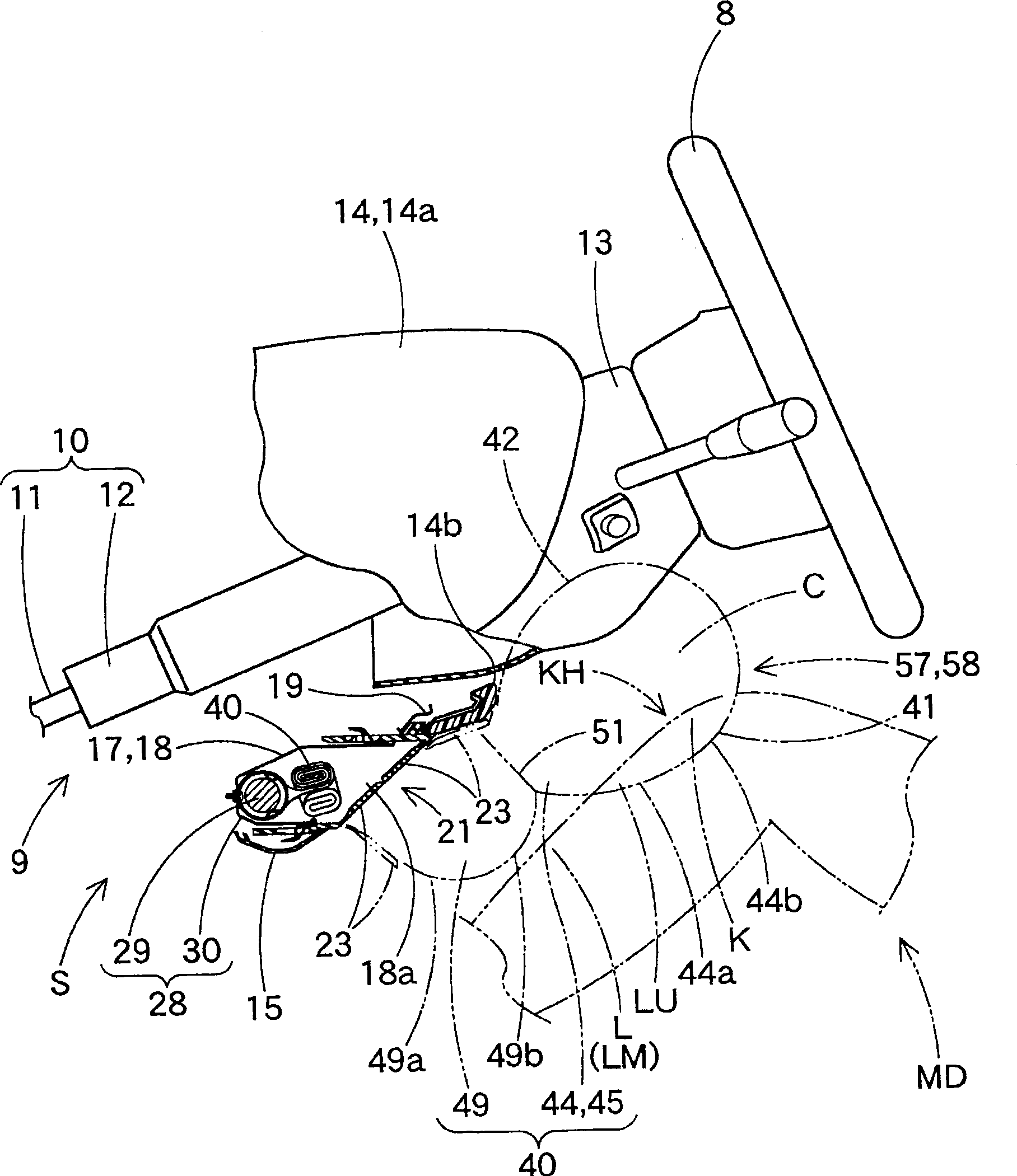
[0053] The knee protection airbag 40 according to the first embodiment is used in the knee protection airbag device S such as figure 1 , 4 As shown, it is disposed on the vehicle front side of the driver MD, that is, below the steering column 9, so that the knee K of the driver MD as a passenger can be protected.

[0054] In addition, the steering column 9 such as figure 1 As shown, there are: a steering column main body 10 connected to the steering wheel 8 ; and a steering column cover 13 arranged to cover the steering column main body 10 below the steering wheel 8 . The steering column main body 10 has a main shaft 11 and a steering column tube 12 covering the periphery of the main shaft 11. The steering column cover 13 has a substantially rectangular tube shape made of synthetic resin, covers the steering column main body 10, and protrudes rearward from an instrument panel 14 (see Figure 4 ).

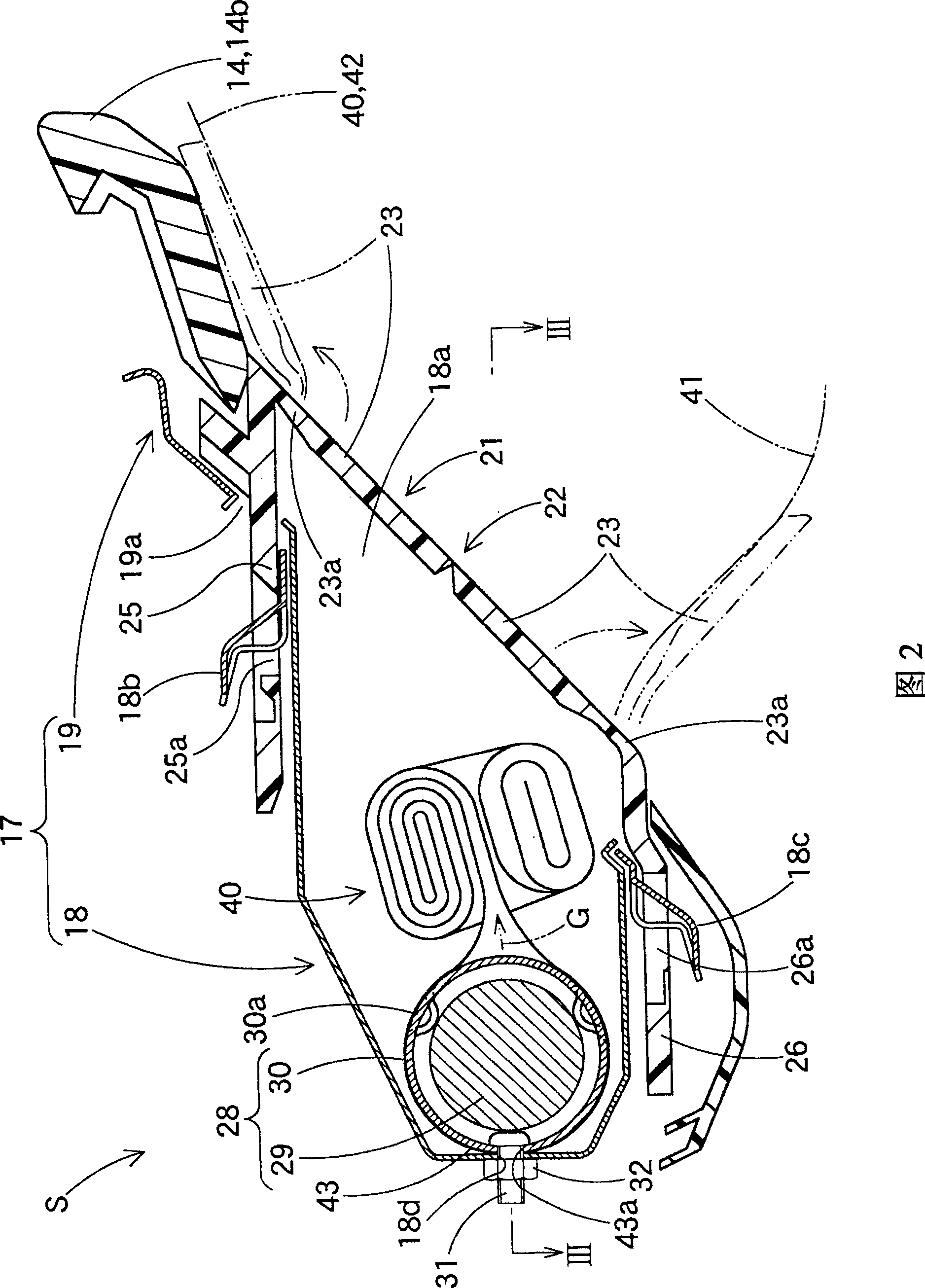
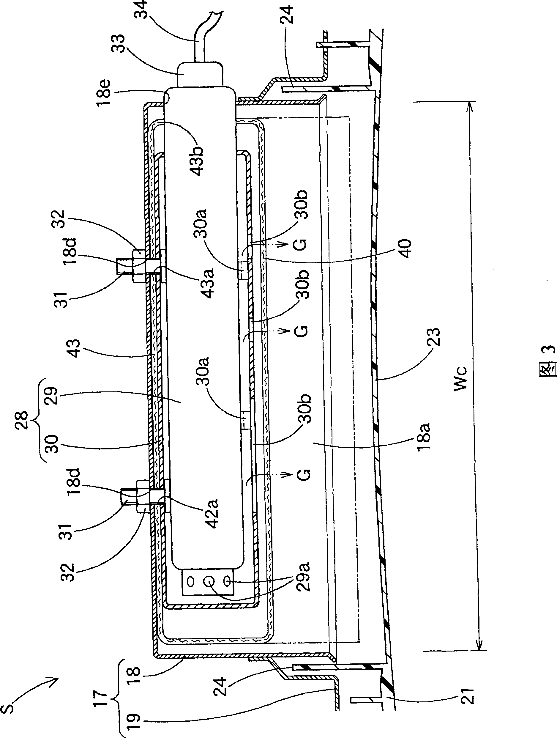
[0055] In addition, the airbag device S for knee protection such as figure ...

Embodiment approach 2

[0089] The airbag 40A of Embodiment 2 is, for example, Figure 14 As shown, similar to Embodiment 1, it is used in the airbag device S for knee protection. This airbag device S for knee protection is the same as that of the first embodiment, except for the airbag 40A, and is constituted by the following components: an inflator 28 which supplies the inflation gas G to the airbag 40A; The airbag 40 and the inflator 28 are opened on the vehicle rear side; and the airbag cover 21 covers the vehicle rear side of the opening 18 a of the casing 17 .

[0090] The airbag 40A of Embodiment 2 differs from the airbag 40 of Embodiment 1 only in that it has a second tether 52 . That is, the airbag 40A as Figure 15 As shown in 17 and 17, similarly to Embodiment 1, it is formed of a woven fabric made of flexible polyester or polyamide threads, and the shape when the expansion is completed is such that the width dimension in the left-right direction on the lower side is reduced. The basebo...


PUM


Abstract

An airbag (40) for knee protection internally includes a first tether (51) that connects a knee-side wall (41) and a vehicle body side wall (42) by a connecting distance (TL1) of 50 to 90 mm and partitions the airbag (40) into an upper inflatable chamber (44) and a lower inflatable chamber (49). The mainstreams of inflation gas heading to the upper inflatable chamber (44) from the lower (49) are located proximate left and right ends of the airbag (40). The upper inflatable chamber (44) has an outer diameter (D1) of 150 to 220 mm at full airbag inflation. The lower inflatable chamber (49) includes on the vehicle body side wall (42) a mounting portion (43) by which the airbag (40) is secured to the case and is designed such that a top (49b) of its rear face (49a) is dislocated forward relative to that of the upper inflatable chamber (44) by 10 to 70 mm at full inflation of the airbag.

Description

technical field [0001] The present invention relates to a knee protection airbag, which is suitable for an airbag device for protecting the knees of passengers such as a seated driver or a passenger in a passenger seat when a vehicle collides. Background technique [0002] At present, as a knee protection airbag, it is formed into a flat bag shape in which the outer peripheral edges of the knee side wall and the vehicle body side wall of the same external shape are connected to each other, so that the airbag can be inflated into a plate shape, thereby being able to protect the passenger's knee. An airbag during inflation is placed in the gap between the front knee and the vehicle body side member, and a strap is placed to limit the distance between the knee side wall and the vehicle body side wall (see JP-A-2006-131186) . [0003] In addition, the volume of the existing knee protection airbag is small, 15-20L, so that it can be arranged in the narrow gap between the knee an...

Claims


Application Information

Patent Timeline
Patent Type & Authority Applications(China)
IPC IPC(8): B60R21/16B60R21/231B60R21/20B60R21/206B60R21/2338B60R21/235
Inventor 今枝宽树榊田克己
Owner TOYODA GOSEI CO LTD
Learn More