Refining device and method for removing liquid steel inclusions in continuous casting tundish

A continuous casting tundish and refining device technology, applied in the iron and steel metallurgical continuous casting tundish field, can solve the problems of argon gas waste, cost increase, limited ability of argon bubbles to capture and remove inclusions, etc., to prolong service life and improve Cleanliness, effect of improving the ability to capture and remove inclusions

Active Publication Date: 2014-06-18
LAIWU STEEL YINSHAN SECTION CO LTD
View PDF10 Cites 18 Cited by
  • Summary
  • Abstract
  • Description
  • Claims
  • Application Information

AI Technical Summary

Problems solved by technology

[0005] Although the permeable brick air curtain retaining wall of the above two patent documents can remove the inclusions in the molten steel to a certain extent and purify the molten steel, there are still the following technical defects: the air blowing volume of the permeable brick is limited, and it cannot be blown On the slag opening surface, the blowing volume is large, and the steel slag surface is easily blown away to cause secondary oxidation of molten steel slag and molten steel. Therefore, the argon bubbles formed by the air curtain wall have limited ability to capture and remove inclusions. Compared with the same period, the traditional flow control device is used to improve There is no superiority in the flow characteristics of molten steel and the removal of inclusions, and it cannot meet the control requirements of high-purity

Method used


Image

  • Refining device and method for removing liquid steel inclusions in continuous casting tundish
  • Refining device and method for removing liquid steel inclusions in continuous casting tundish
  • Refining device and method for removing liquid steel inclusions in continuous casting tundish

Examples


Embodiment 1

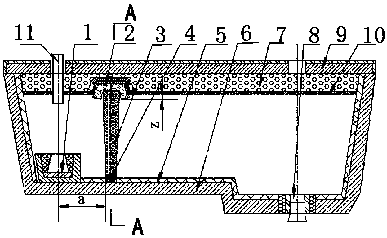
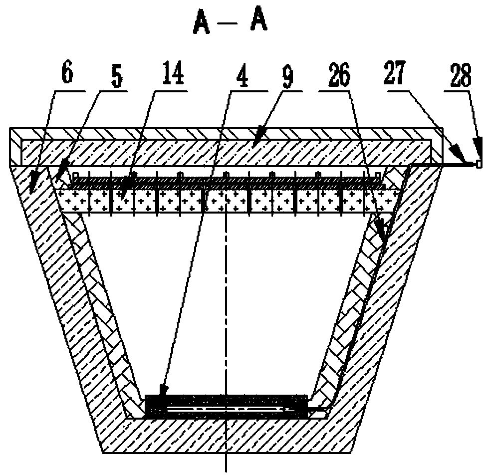
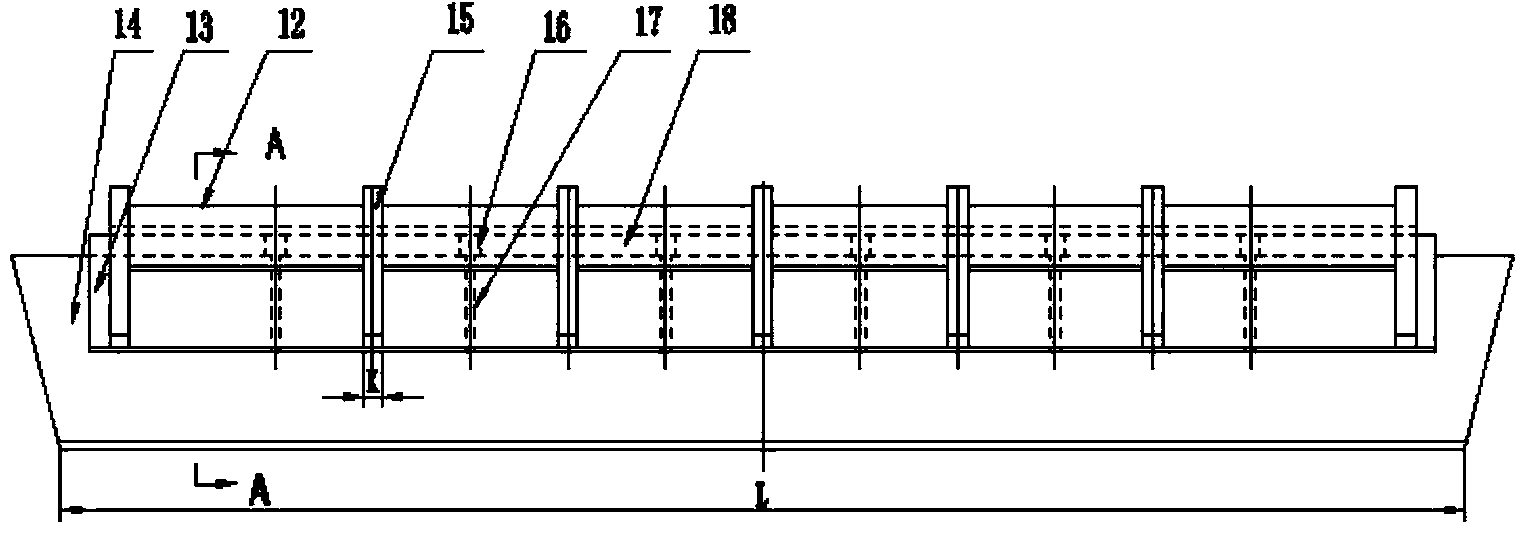
[0048] A refining device for removing inclusions in molten steel in a continuous casting tundish, with a structure such as Figure 1-Figure 7 As shown, it includes a turbulence controller 1, a refining cover 2, and an air curtain brick 4. The turbulence controller 1 is installed on the inner side of the working lining of the tundish wall in the injection impact area of ​​the tundish. Line coincides, the air curtain permeable brick 4 is fixed on the permanent lining 6 at the bottom of the tundish, and partially embedded in the working lining 5 at the bottom of the tundish, the refining cover 2 is located directly above the air curtain permeable brick 4 and is in contact with the air The curtain air brick 4 is opposite, the longitudinal center line of the refining cover 2 coincides with the longitudinal center line of the air curtain air brick 4, the two sides of the refining cover 2 are fixed on the permanent lining 6 of the tundish wall, the refining cover 2, Including the out...

Embodiment 2

[0053] The refining device for removing molten steel inclusions in the continuous casting tundish as described in Example 1, the difference is:

[0054] The depth z of the lower end of the dipping cover 14 immersed in the molten steel is 50 mm, and the distance a between the center line of the turbulence controller 1 and the center of the air curtain permeable brick 4 is 400 mm.

[0055] The hollow in the middle of the turbulence controller core 30 is in the shape of a truncated cone with the diameter of the upper end smaller than that of the lower end. The diameter d of the upper port circle in the middle hollow of the turbulence controller core 30 is 300 mm, and the diameter D of the lower port circle is 360 mm.

[0056] The angle between the plane where the side plate is located and the plane where the transverse plate is located is 120°.

Embodiment 3

[0058] The refining device for removing molten steel inclusions in the continuous casting tundish as described in Example 1, the difference is:

[0059] The depth z of the lower end of the dipping cover 14 immersed in the molten steel is 40 mm, and the distance a between the center line of the turbulence controller 1 and the center of the air curtain permeable brick 4 is 300 mm.

[0060] The hollow in the middle of the turbulence controller core 30 is in the shape of a truncated cone with the diameter of the upper end smaller than that of the lower end. The diameter d of the upper port circle in the middle hollow of the turbulence controller core 30 is 320 mm, and the diameter D of the lower port circle is 380 mm.

[0061] The angle between the plane where the side plate is located and the plane where the transverse plate is located is 130°.


PUM

PropertyMeasurementUnit
Diameteraaaaaaaaaa
Diameteraaaaaaaaaa
Widthaaaaaaaaaa

Abstract

The invention relates to a refining device and method for removing liquid steel inclusions in a continuous casting tundish. The refining device comprises a turbulence controller, a refining cover and air curtain ventilation bricks. The two side ends of the refining cover are fixed to a permanent lining on the wall of the tundish, the lower end of the refining cover is immersed into liquid steel below a steel slag layer inside the tundish, the refining cover is located over the air curtain ventilation bricks and is opposite to the air curtain ventilation bricks, a gas channel is formed in the body of the refining cover, the two ends of the gas channel are communicated with a gap between a tundish cover and the steel slag layer inside the tundish, gas exhaust holes communicated with the gas channel are formed in the body of the refining cover and are opposite to the air curtain ventilation bricks, large-flow argon is blown in through the air curtain ventilation bricks, an air curtain barrier with the large continuous intensity is formed between the air curtain ventilation bricks and the refining cover, the inclusions are captured and are adsorbed and removed by the steel slag layer, the argon flows through the gas channel and forms argon seal between the steel slag layer inside the tundish and the tundish cover, the steel slag face is protected, secondary oxidation of liquid steel is avoided, the cleanliness of the liquid steel is greatly improved, and the 0.5 level of the four kinds of inclusions in LHG2 steel reaches more than 90%.

Description

technical field [0001] The invention relates to a refining device and a refining method for removing liquid steel inclusions in a continuous casting tundish, belonging to the technical field of iron and steel metallurgy continuous casting tundish. Background technique [0002] The continuous casting tundish air curtain retaining wall technology is a new technology developed at the end of the 20th century to remove non-metallic inclusions in the molten steel in the continuous casting tundish. Bricks are placed at a certain position at the bottom of the tundish, and argon gas is blown in, and the argon gas floats through the breathable brick to form a micro-bubble air curtain barrier. The purpose of removing inclusions and purifying molten steel. [0003] For example, Chinese patent document CN101121199 (application number: 200710121680.2) discloses a method for removing non-metallic inclusions in the continuous casting tundish air curtain retaining wall, placing breathable b...

Claims


Application Information

Patent Timeline
IPC IPC(8): B22D11/117
Inventor 武光君郭伟达
Owner LAIWU STEEL YINSHAN SECTION CO LTD
Why Eureka
Try Eureka