Pneumatic tool

a technology of pneumatic tools and tools, applied in the field of pneumatic tools, can solve the problems of reducing the utility or preclude the use of tools, hammers, and tool components being subjected to large destructive forces, so as to reduce the and reduce the kinetic energy of the impactor devi

Inactive Publication Date: 2005-08-23
KIRSCH PAUL
View PDF36 Cites 17 Cited by
  • Summary
  • Abstract
  • Description
  • Claims
  • Application Information

AI Technical Summary

Benefits of technology

[0006]The present invention provides a tool for impacting a workpiece. The tool comprises a casing having a proximal end and a distal end with a chamber defined therebetween. An impactor device is slidable within the chamber along an operational axis. A valve system slides the impactor device within the chamber by selectively introducing and releasing fluid pressure into and out from the chamber. An energy absorbing mechanism reduces kinetic energy of the impactor device as the impactor device slides within the chamber. The energy absorbing mechanism comprises a sleeve that slides along the casing and first and second pressure chambers to reduce the kinetic energy of the impactor device. The first pressure chamber is defined between the impactor device and the sleeve and the second pressure chamber is defined between the casing and the sleeve. The first pressure chamber reduces the energy of the impactor device in a first stage immediately after movement thereof by compressing pressurized fluid within the first pressure chamber. The second pressure chamber reduces the energy of the impactor device in a second stage after compression in the first pressure chamber and when the impactor device impacts the sleeve.

Problems solved by technology

Typically, however, pneumatic tools for impacting a workpiece by delivering hammering blows, e.g., pneumatic hammers, have characteristics that detract from their utility or preclude their use in some applications such as breaking off casting risers on a production line, or seating large press-fit assemblies.
However, some applications, such as breaking off casting risers on a production line, require the impactor device to carry high kinetic energy throughout a relatively long stroke to impact workpieces at varying distances.
In such an event, without an energy absorbing mechanism, tool components can be subjected to large destructive forces.

Method used


Image

  • Pneumatic tool
  • Pneumatic tool
  • Pneumatic tool

Examples


Embodiment Construction

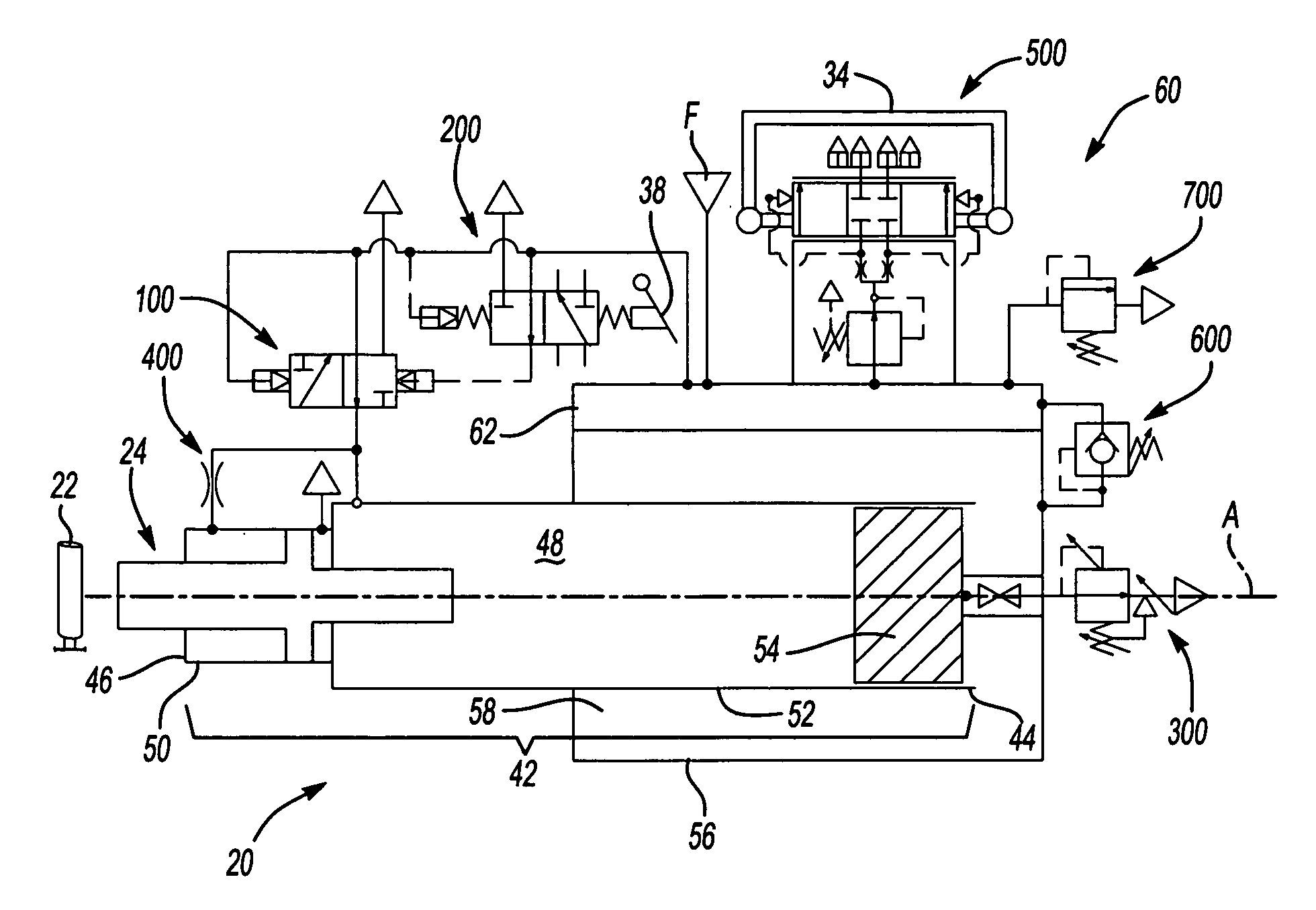
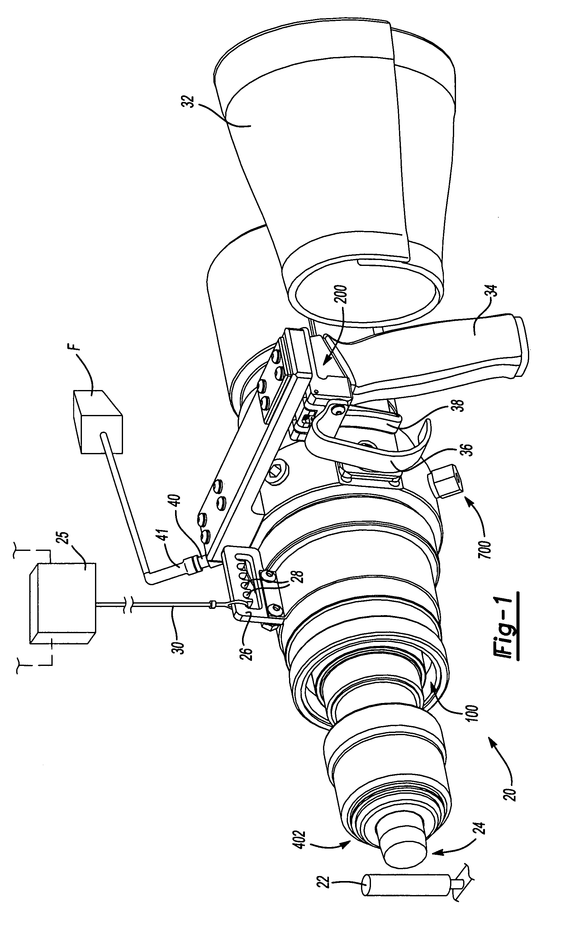
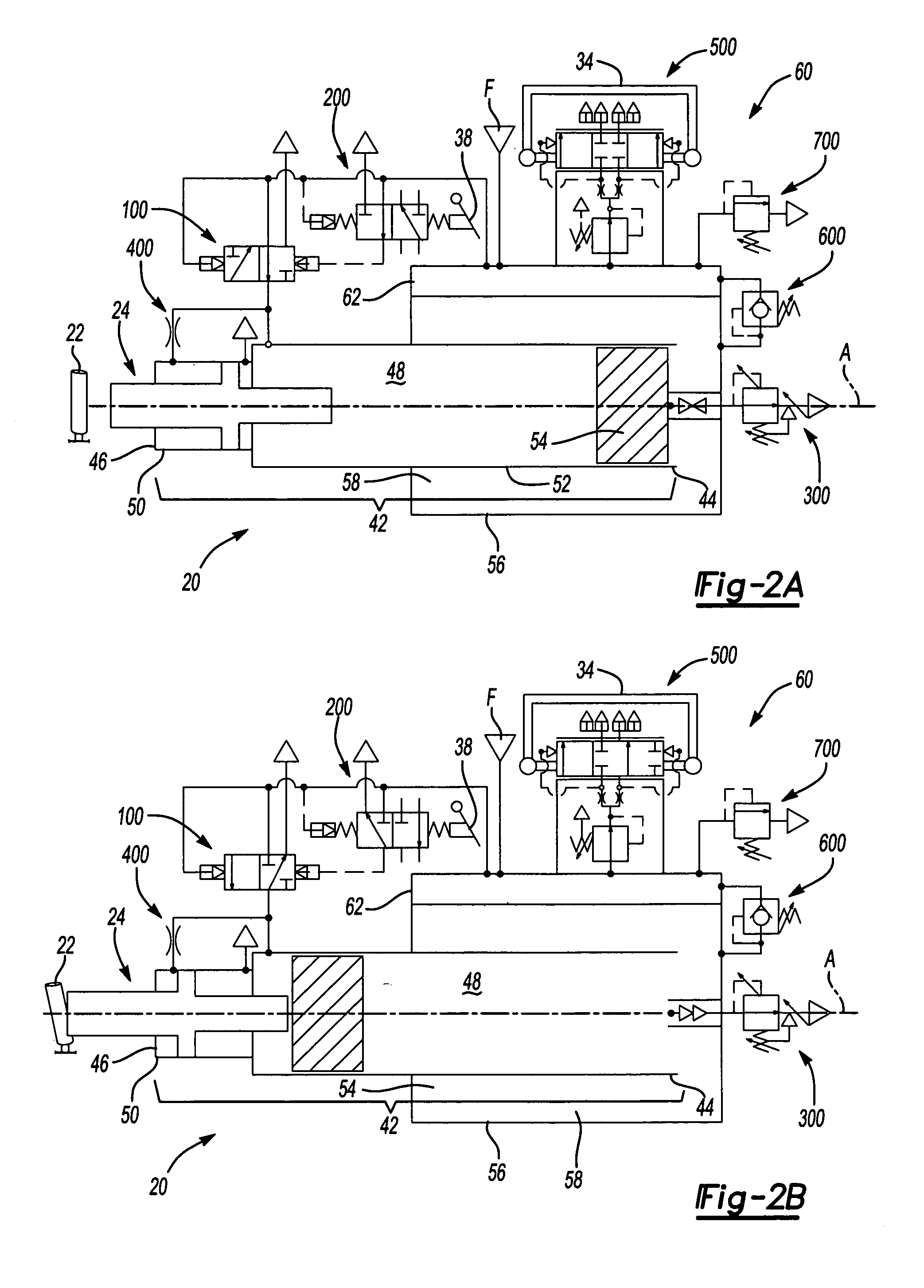
[0028]Referring to the Figures, wherein like numerals indicate like or corresponding parts throughout the several views, a tool for impacting a workpiece 22 is generally shown at 20. The tool 20 is preferably a pneumatic impacting tool for fracturing a gate or riser from a casting after a foundry pouring process. Of course, the tool 20 may be used for other applications including, but not limited to, breaking concrete or other similar demolition, driving fasteners in construction applications, seating large press-fit assemblies, and the like. The tool 20 is powered by a conventional pressurized fluid source F, e.g., an air compressor.

[0029]Referring to FIG. 1, the tool 20 is shown fully assembled and ready for use. A tool bit 24 is shown in a starting position. Upon actuation, the tool bit 24 slides distally to impact the workpiece 22. An adjuster plate 26 may be used to suspend the tool 20 from a tool balancer 25 to provide added versatility and maneuverability in positioning the t...


PUM


Abstract

A pneumatic tool (20) for impacting a workpiece (22) is provided. The tool (20) comprises a casing (42) defining a chamber (48). A piston (54) is slidable within the chamber (48) along an operational axis (A). An exhaust valve (100) controlled by a pilot valve (200) slides the piston (54) by selectively introducing and releasing pressurized fluid into and out from the chamber (48). A tool bit (24) is slidable within the chamber (48) to impact the workpiece (22). Kinetic energy is transferred to the tool bit (24) from the piston (54) via an impact from the piston (54) as the piston (54) slides within the chamber (48). An energy absorbing mechanism (402) reduces the kinetic energy of the tool bit (24) after impact by the piston (54). The energy absorbing mechanism comprises a sleeve (404) that slides along the casing (42) and first (412) and second (414) pressure chambers that dissipate the kinetic energy of the tool bit (24) in multiple stages.

Description

CROSS-REFERENCE TO RELATED APPLICATIONS[0001]This application claims the benefit of U.S. provisional patent application Ser. Nos. 60 / 430,611, filed Dec. 3, 2002; 60 / 430,550, filed Dec. 3, 2002; and 60 / 430,610, filed Dec. 3, 2002, all of which are herein incorporated by reference.FIELD OF THE INVENTION[0002]The present invention generally relates to a pneumatic tool having an impactor device, e.g., piston and tool bit, for impacting a workpiece. More specifically, the present invention relates the pneumatic tool having an energy absorbing mechanism for absorbing kinetic energy of the impactor device during use to prevent the destruction of components of the pneumatic tool, such as during a dry fire, while otherwise providing a high impacting force to the workpiece.BACKGROUND OF THE INVENTION[0003]Pneumatic tools offer a “best-fit” solution in many applications because of their safety, reliability, and simplicity. Typically, however, pneumatic tools for impacting a workpiece by delive...

Claims


Application Information

Patent Timeline
Patent Type & Authority Patents(United States)
IPC IPC(8): B25D9/00B25D9/02B25D9/08B25D9/16B25D17/24
CPCB22D31/00B25D9/08B25D9/16B25D9/20B25D17/245
Inventor KIRSCH, PAUL
Owner KIRSCH PAUL
Why Eureka
Try Eureka