Mass spectrometer

Active Publication Date: 2010-07-08
SHIMADZU CORP
View PDF16 Cites 20 Cited by
  • Summary
  • Abstract
  • Description
  • Claims
  • Application Information

AI Technical Summary

Benefits of technology

[0027]With the mass spectrometer according to the present invention, even in the case where an ion comes in contact with a collision induced dissociation gas inside the collision cell and the kinetic energy is decreased for example, the precursor ion and the product ions generated by a dissociation are assisted in their progress, which can prevent the ions' substantial delay

Problems solved by technology

Hence, if the ion's time delay is significant due to the speed reduction, an ion which should normally pass through the third-stage quadrupole electrodes 15 might not be able to pass through it, which causes a degradation in the detection sensitivity.
Moreover, since it takes time for an ion to reach the detector 16, the time interval of the repeated analysis is required to be previously determined in view of such a situation, which might cause an omission of analysis information in a multi-component analysis.
However, if each rod electrode of a radio-frequency ion guide is obliquely disposed at different angles from each other or if an auxiliary electrode is used in order to form a direct current electric field having a pote

Method used


Image

  • Mass spectrometer
  • Mass spectrometer
  • Mass spectrometer

Examples


first embodiment

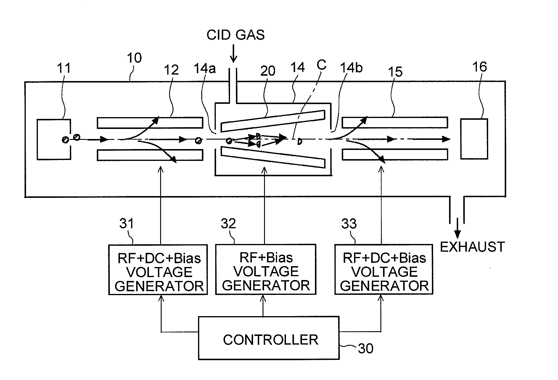
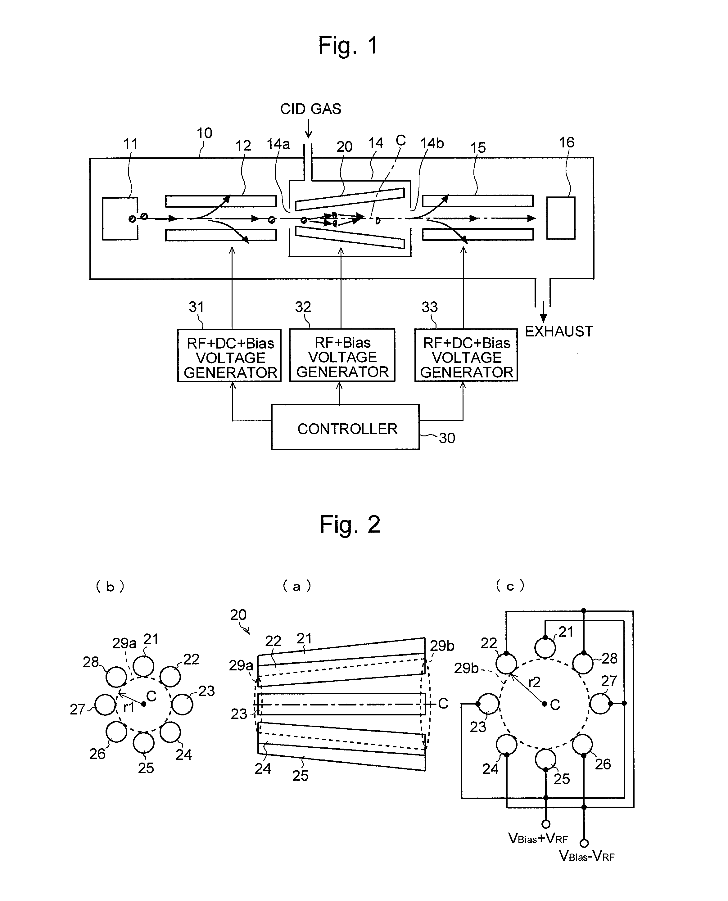
[0047]An MS / MS mass spectrometer which is an embodiment (the first embodiment) of the present invention will be described with reference to the figures. FIG. 1 is an overall configuration diagram of the MS / MS mass spectrometer according to this embodiment, and FIG. 2 is an external plain view of an ion guide provided in the collision cell in the MS / MS mass spectrometer of the present embodiment. The same components as in the conventional configuration as illustrated in FIG. 11 are indicated with the same numerals and the detailed explanations are omitted.

[0048]In the MS / MS mass spectrometer of the present embodiment, as in the conventional configuration, a collision cell 14 is provided between the first-stage quadrupole electrodes 12 and the third-stage quadrupole electrodes 15 in order to generate a variety of product ions by dissociating a precursor ion. This collision cell 14 is an almost hermetically-closed structure except for an ion injection aperture 14a and ion exit aperture...

second embodiment

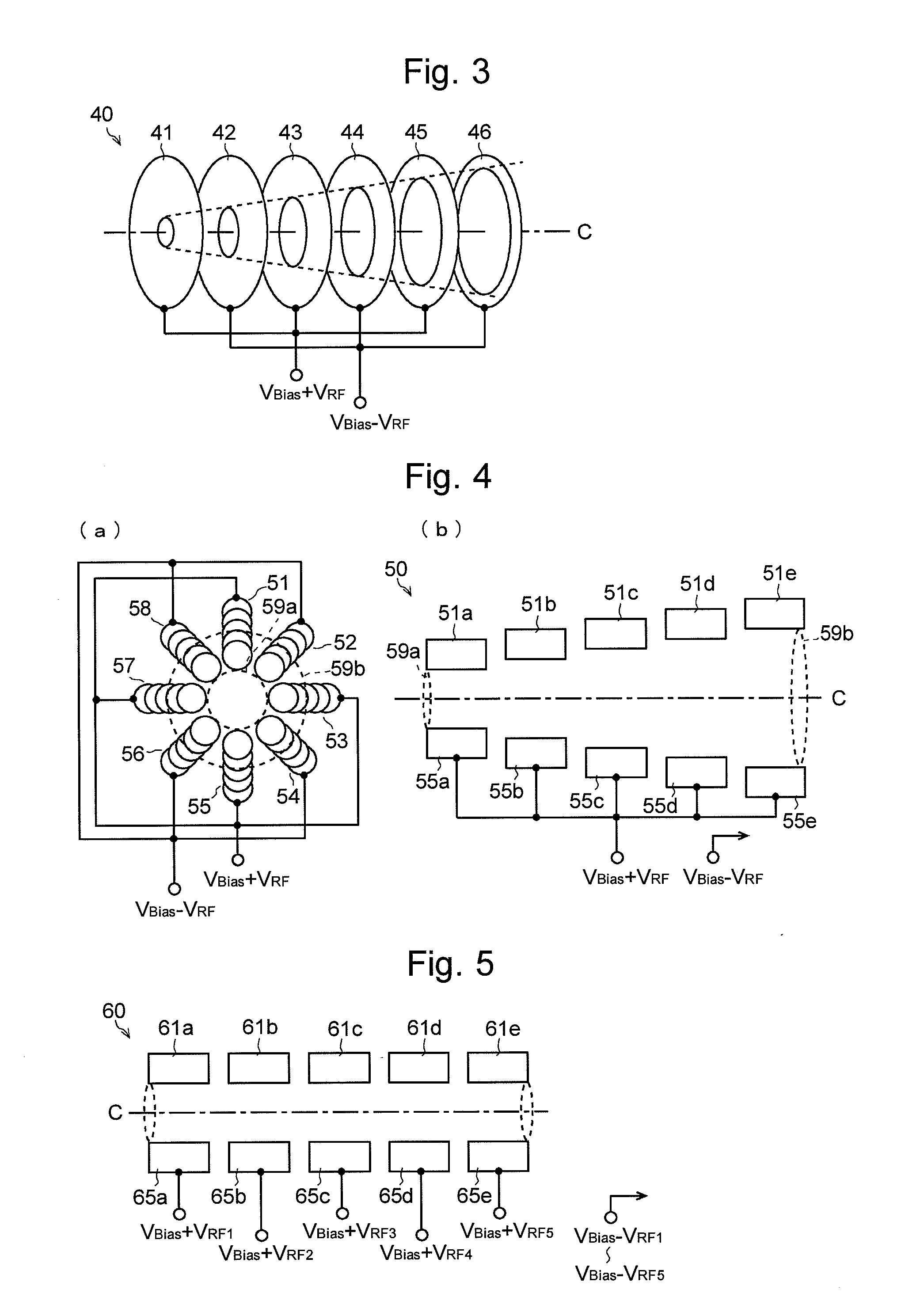
[0059]The radio-frequency ion guide 40 illustrated in FIG. 3 is composed of a plurality (six in this example) of plate electrodes 41 through 46 arranged along the ion optical axis C. Each of the plate electrodes 41 through 46 has a circular opening centering on the ion optical axis C, and the radius of the opening increases in a stepwise manner toward the ion's traveling direction. This electrode design is similar to that of the first embodiment in which the radius of the inscribed circle of a plurality of rod electrodes gradually increases, and hence brings about the same effect as in the first embodiment. In this case, the radio-frequency voltage VRF is applied to the plate electrodes in such a manner that the polarity is reversed for two electrodes neighboring along the ion optical axis C.

third embodiment

[0060]The radio-frequency ion guide 50 illustrated in FIG. 4 can be considered to be composed of eight rod electrodes disposed in such a manner as to surround the ion optical axis C as in the first embodiment. However, the substance of each rod electrode is not a single electrode but a virtual rod electrode (e.g. numeral 51) composed of a plurality (five in this example) of segmented rod electrodes (e.g. numerals 51a through 51e) which are separated in the direction of the ion optical axis C. That is, eight virtual rod electrodes 51 through 58 are disposed in such a manner as to surround the ion optical axis C. In each of the virtual rod electrodes 51 through 58, the segmented rod electrodes (e.g. numerals 51a through 51e) are disposed in such a manner that their distance from the ion optical axis C increases in a stepwise manner toward the ion's traveling direction. Therefore, the magnitude or depth of the pseudopotential does not have a smoothly slanted gradient as in the first em...


PUM


Abstract

A radio-frequency ion guide (20) for converging ions by a radio-frequency electric field and simultaneously transporting the ions into the subsequent stage is composed of eight rod electrodes (21 through 28) arranged in such a manner as to surround an ion optical axis (C). Each of the rod electrodes (21 through 28) is disposed at a tilt with respect to the ion optical axis (C) so that the radius r2 of the inscribed circle (29b) at the end face of the ion exit side is larger than the radius r1 of the inscribed circle (29a) at the end face of the ion injection side. Accordingly, the gradient of the magnitude or depth of the pseudopotential is formed in the ion's traveling direction in the space surrounded by the rod electrodes (21 through 28). Ions are accelerated in accordance with this gradient. Therefore, even in the case where the gas pressure is relatively high and ions have many chances to collide with gas, it is possible to moderate the ions' slowdown and prevent the ions' delay and stop.

Description

TECHNICAL FIELD[0001]The present invention relates to a mass spectrometer. More precisely, it relates to an ion transport optical system for transporting an ion into the subsequent stage under a relatively high gas pressure.BACKGROUND ART[0002]A well-known mass-analyzing method for identifying a substance having a large molecular weight and for analyzing its structure is an MS / MS analysis (or tandem analysis). FIG. 11 is a schematic configuration diagram of a general MS / MS mass spectrometer disclosed in Patent Documents 1 and other documents.[0003]In this MS / MS mass spectrometer, three-stage quadrupole electrodes 12, 13, and 15 each composed of four rod electrodes are provided, inside the analysis chamber 10 which is vacuum-evacuated, between an ion source 11 for ionizing a sample to be analyzed and a detector 16 for detecting an ion and providing a detection signal in accordance with the amount of ions. A voltage ±(U1+V1·cosωt) is applied to the first-stage quadrupole electrodes 12...

Claims


Application Information

Patent Timeline
IPC IPC(8): H01J49/26H01J49/24H01J49/06
CPCH01J49/0045H01J49/063
Inventor OKUMURA, DAISUKEITOI, HIROTO
Owner SHIMADZU CORP
Why Eureka
Try Eureka