
Airtightness detection system

A technology of air tightness detection and detection device, which is applied in the direction of using liquid/vacuum degree for liquid tightness measurement, by measuring the acceleration and deceleration rate of fluid, etc., can solve problems such as inability to meet, manual assistance, and inability to achieve detection effect, etc. achieve the effect of liberating labor

Inactive Publication Date: 2018-12-28
GUANGYUAN XINYUAN EQUIP MFG
View PDF0 Cites 0 Cited by
  • Summary
  • Abstract
  • Description
  • Claims
  • Application Information

AI Technical Summary

Problems solved by technology

Although these machines have the function of detection, manual assistance is required to replace the parts to be detected and determine the qualified and unqualified parts
In addition, such a detection method cannot achieve the expected detection effect and cannot meet the actual needs.

Method used


Image

  • Airtightness detection system
  • Airtightness detection system
  • Airtightness detection system

Examples


Embodiment Construction

[0027] The present invention will be further described in detail below in conjunction with the accompanying drawings and specific embodiments.

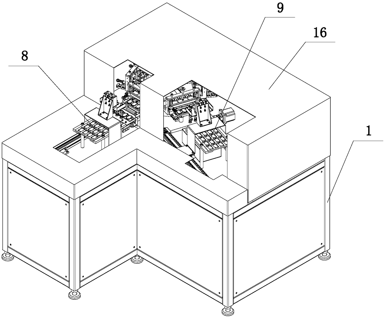
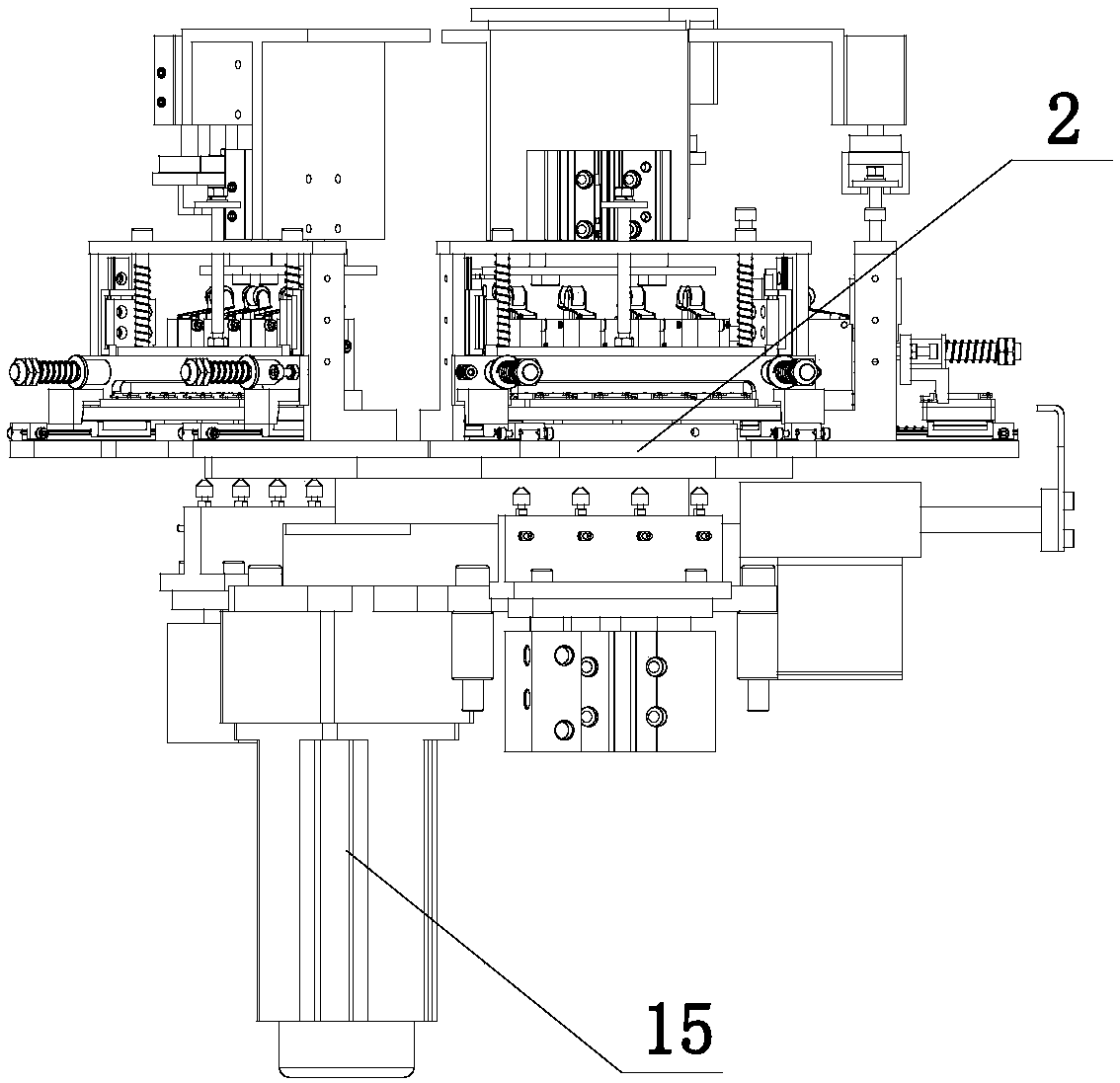
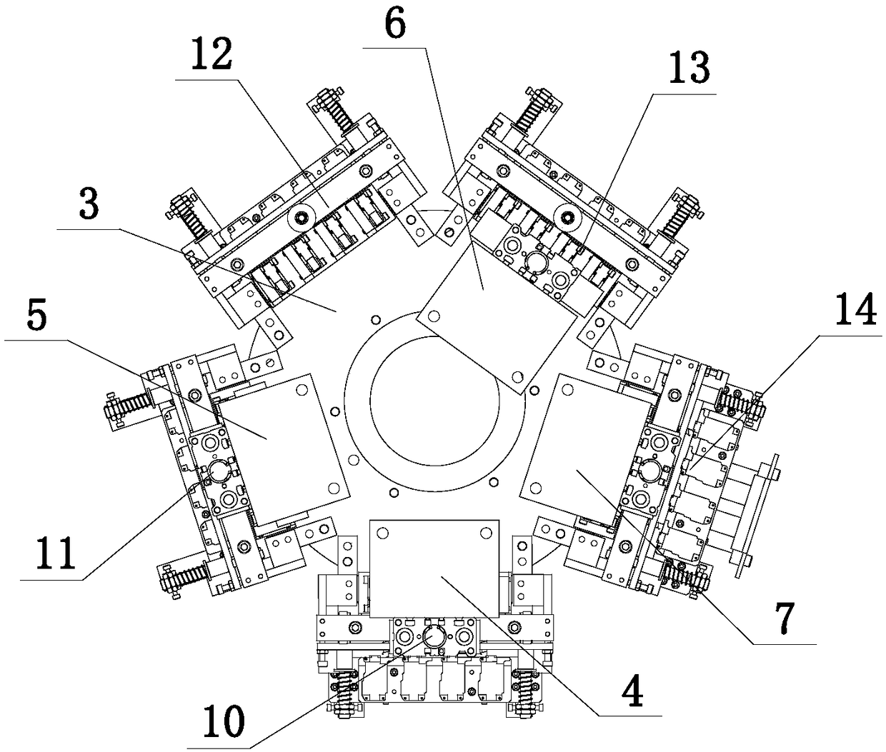
[0028] Such as figure 1 — Figure 10 As shown, an airtight detection system includes a frame 1, a compressed air storage tank and a pressure detection device, the upper surface of the frame 1 is provided with a mounting plate 2, and the top of the mounting plate 2 is provided with a rotary table 3. The upper surface of the mounting plate 2 is respectively provided with a pressing assembly 4, an inflating assembly 5, a detection assembly 6 and a releasing assembly 7 around the rotating table 3, and the upper surface of the mounting plate 2 is provided with an upper part moving Component 8, the position corresponding to the release component 7 on the upper surface of the installation plate 2 is provided with a lower part moving component 9, and the upper surface of the rotary table 3 is from one end close to the upper part moving compo...


PUM


Abstract

The invention discloses an airtightness detection system, comprising a rack, a compressed air storage tank and a pressure detection device. A mounting plate is arranged on an upper surface of the rack, a rotating table is arranged above the mounting plate, a pressing assembly, an inflation assembly, a detection assembly and a releasing assembly are respectively arranged on the upper surface of themounting plate around the rotating table. An upper piece moving assembly is arranged at a position of the upper surface of the mounting plate corresponding to the pressing assembly, a lower piece moving assembly is arranged at a position of the upper surface of the mounting plate corresponding to the releasing assembly. A first rotating assembly, a second rotating assembly, a third rotating assembly, a fourth rotating assembly and a fifth rotating assembly are sequentially arranged on the upper surface of the rotating table from one end close to the upper piece moving assembly to one end close to the lower piece moving assembly. According to the airtightness detection system, steps of assembly mounting, compressing, inflating, detecting, releasing and assembly dismounting can be linked up, and manpower is free to some extent.

Description

technical field [0001] The invention belongs to the field of airtight detection, and in particular relates to an airtight detection system. Background technique [0002] During the processing of auto parts, they will be tested for air tightness. At present, the common air tightness detection is carried out by simple machinery. Although these machines have the function of inspection, manual assistance is required to replace the parts to be inspected and determine the qualified and unqualified parts. In addition, such a detection method cannot achieve an expected detection effect and cannot meet actual needs. Contents of the invention [0003] The technical problem to be solved by the present invention is to provide an airtight detection system for the above-mentioned deficiencies in the prior art, which can connect the steps of loading, pressing, inflating, testing, releasing and unloading to a certain extent. Artificial. [0004] The technical solution adopted in the p...

Claims


Application Information

Patent Timeline
IPC IPC(8): G01M3/26
CPCG01M3/26
Inventor 杨毅王琦袁洪武蒲建军徐军王宪秋
Owner GUANGYUAN XINYUAN EQUIP MFG
Features
  • Generate Ideas
  • Intellectual Property
  • Life Sciences
  • Materials
  • Tech Scout
  • Unparalleled Data Quality
  • Higher Quality Content
  • 60% Fewer Hallucinations
Learn More