
A dimmable LED driving control circuit

A technology of LED drive and control circuit, applied in the field of control circuit, can solve the problems of inability to meet the needs of use, single dimming method, etc.

Pending Publication Date: 2018-12-28
厦门思泰克智能科技股份有限公司
View PDF0 Cites 0 Cited by
  • Summary
  • Abstract
  • Description
  • Claims
  • Application Information

AI Technical Summary

Problems solved by technology

In order to improve the efficiency of LED lamps and prolong the life of LED lamps, the switching timing and brightness of the LED light source need to be controlled. The existing conventional LED control circuits on the market adopt a single dimming method and cannot meet the needs of use.

Method used


Image

  • A dimmable LED driving control circuit

Examples


Embodiment Construction

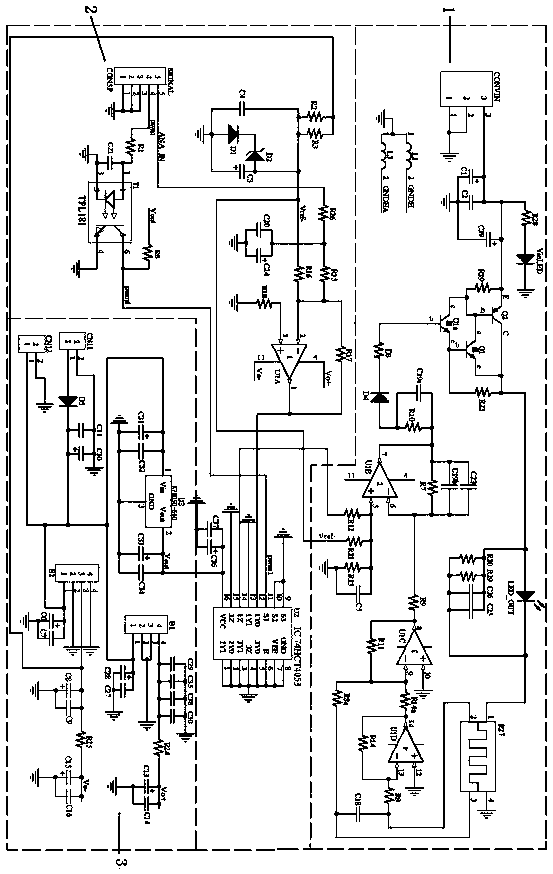
[0014] A dimmable LED drive control circuit, comprising a constant voltage power supply circuit unit 3, a 5V-0V analog signal control circuit unit 2, and an LED lamp constant current drive circuit unit 1; the constant voltage power supply circuit unit 3 is composed of a voltage stabilizing chip U3, Composed of DC / DC converter B1, DC / DC converter B2 and its connection circuit; 5V-0V analog signal control circuit unit 2 is composed of analog switch chip U2, part A of amplifier chip U1, photocoupler T1 and its connection circuit LED lamp constant current drive circuit unit 1 is composed of the B part of the amplifier chip U1, the C part of the amplifier chip U1, the D part of the amplifier chip U1 and its connecting circuit.

[0015]The first pin of the connector CN11 is connected to the positive pole of the diode D5; the negative pole of the diode D5, one end of the capacitor C11, one end of the capacitor C10, the first pin of the connector CN12, one end of the capacitor C31 and ...


PUM


Abstract

A dimmable LED driving control circuit is characterized by comprising a constant voltage power supply circuit unit, a 5V-0V analog signal control circuit unit and an LED lamp constant current drivingcircuit unit. The constant voltage power supply circuit unit is composed of a voltage stabilizer chip U3, a DC / DC converter B1, a DC / DC converter B2 and a connection circuit thereof, wherein, the constant voltage power supply circuit unit comprises a voltage stabilizer chip U3, a DC / DC converter B1 and a DC / DC converter B2; the 5V-0V analog signal control circuit unit is composed of analog switchchip U2, part A of amplifier chip U1, photoelectric coupler T1 and its connection circuit; the LED lamp constant current driving circuit unit is composed of a B part of an amplifier chip U1, a C partof the amplifier chip U1, a D part of the amplifier chip U1 and a connection circuit thereof. The main control board of the invention is provided with an output PWM signal for switching control of theLED, and an output voltage analog signal for controlling the brightness. The circuit can effectively control the LED lamp luminescence according to the input analog signal, and the luminescence brightness is linear with the analog signal.

Description

technical field [0001] The invention relates to the technical field of control circuits, in particular to a dimmable LED drive control circuit. technical background [0002] On the online 3D solder paste inspection equipment (SPI), an optical projection optical path with a 3D projection grating is designed. This optical path requires a 30W high-power and high-brightness LED lamp as a light source. In order to improve the efficiency of LED lamps and prolong the life of LED lamps, the switching timing and brightness of the LED light source need to be controlled. The existing conventional LED control circuits on the market adopt a single dimming method and cannot meet the needs of use. Contents of the invention [0003] The present invention overcomes the defects of the prior art and aims to provide a dimmable LED drive control circuit that controls the LED lamp to emit light through a 5V-0V analog signal and uses a PWM signal to switch the analog signal on and off to control...

Claims


Application Information

Patent Timeline
Patent Type & Authority Applications(China)
IPC IPC(8): H05B33/08H05B44/00
CPCH05B45/14H05B45/00
Inventor 姚征远林福凌张望雄
Owner 厦门思泰克智能科技股份有限公司
Learn More