A split pet feeder

A feeder and split-type technology, which is applied to animal feeding devices, animal houses, animal taming devices, etc., can solve the problems of center of gravity deviation, damage, uneven distribution of food weight, etc., to avoid material jams and prevent The effect of pouring and falling

Active Publication Date: 2020-07-14
浙江企信检测有限公司
View PDF8 Cites 0 Cited by
  • Summary
  • Abstract
  • Description
  • Claims
  • Application Information

AI Technical Summary

Problems solved by technology

[0003] The barrel of the existing pet feeder is generally set with an inclined bottom, and the discharge port is set close to the food tray, and the pet food in the barrel does not get stuck through the external impeller and baffle; when the barrel When there is a lot of food inside, the food close to the outlet will enter the food plate first, and due to the friction between the food, the food on the side away from the outlet will be kept at a higher height, resulting in The vertical surface of the container is sunken and the surrounding area is high, so that the weight distribution of the food in the barrel is uneven, causing the center of gravity to shift, and there is a hidden danger of dumping, resulting in damage and failure to feed pets in time, especially the upper and lower separation of the barrel and the base. pet feeder

Method used


Image

  • A split pet feeder
  • A split pet feeder
  • A split pet feeder

Examples


Embodiment 1

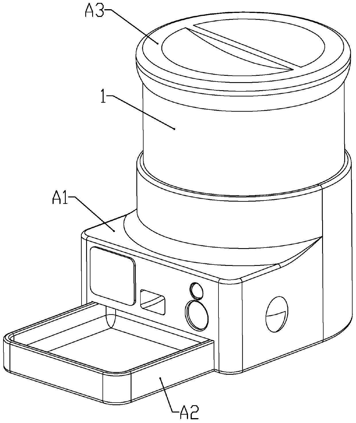
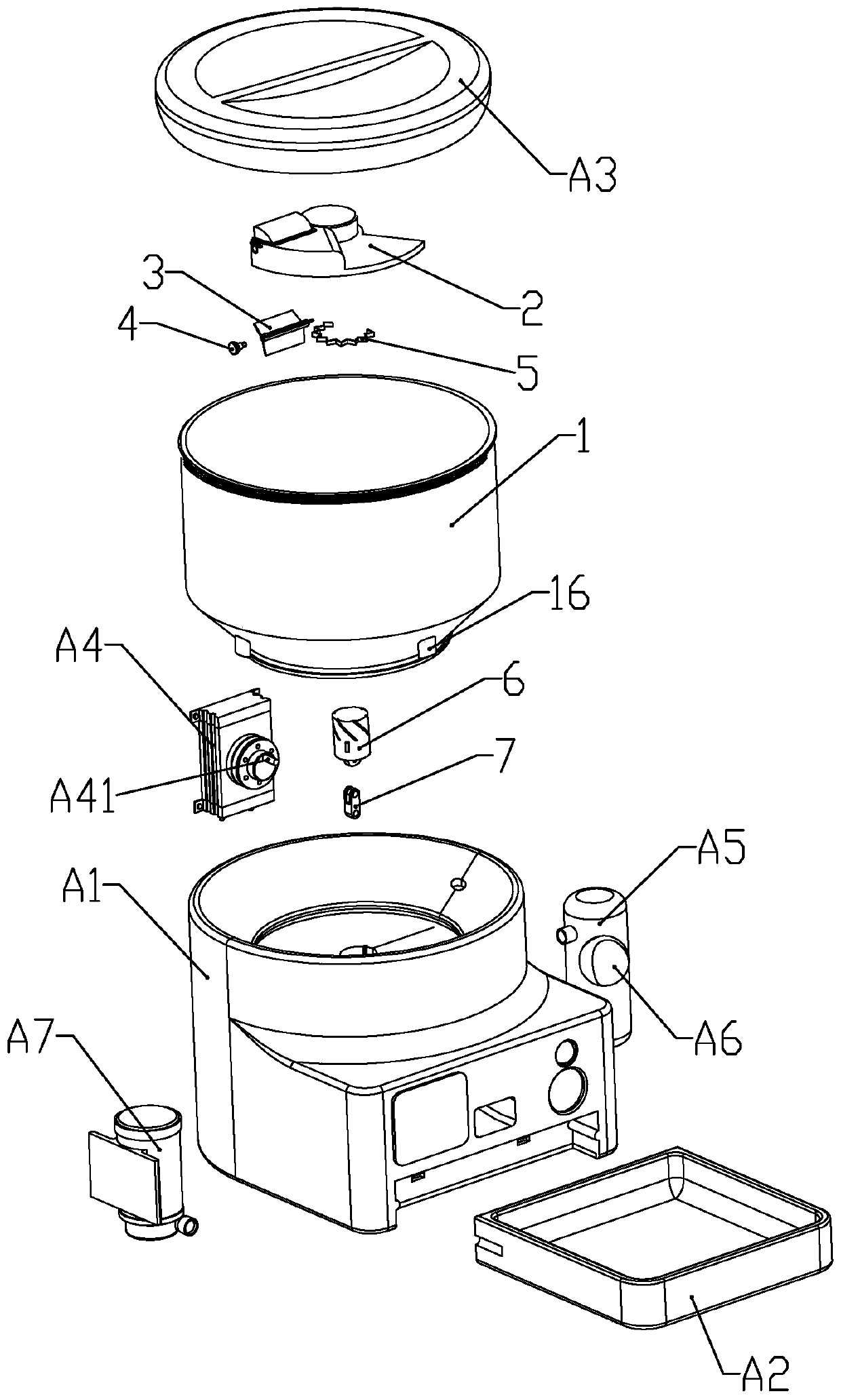
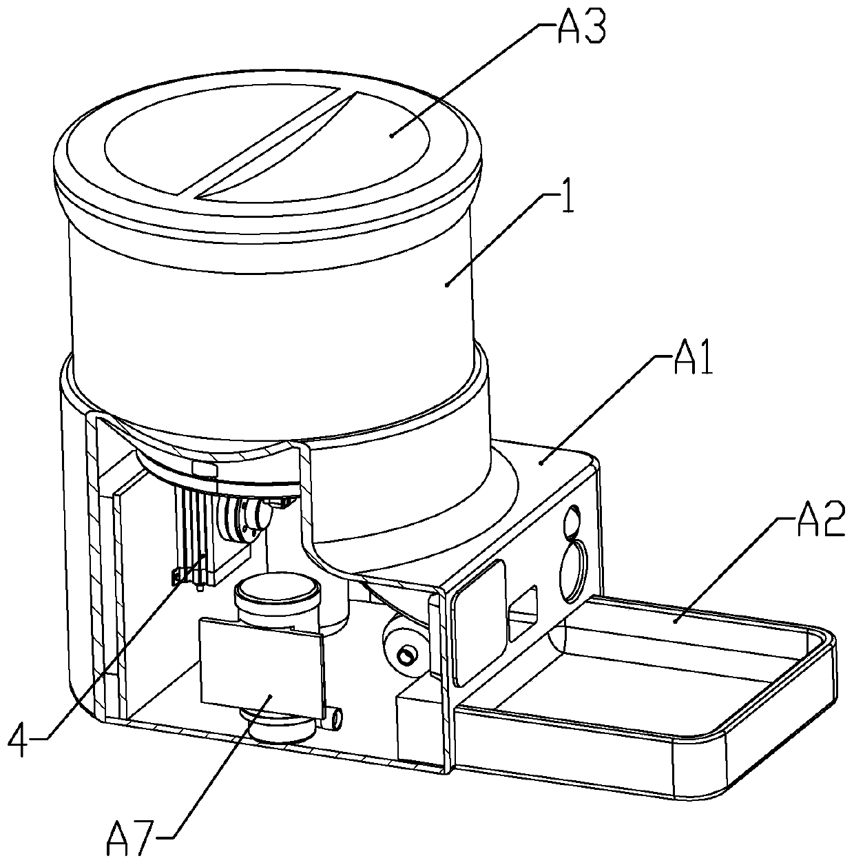
[0042] according to Figure 1 to Figure 8 As shown, a split-type pet feeder described in this embodiment includes a base A1, a barrel 1 detachably installed on the upper end of the base, and a top cover A3 that is movably and sealingly connected to the upper end of the barrel; A food tray A2 is detachably mounted on the lower part of the front end of the base; a booster air pump A7 is installed in the base.

[0043] The lower part of the barrel is in the shape of a truncated cone with a large top and a small bottom; a through hole 11 is formed in the center of the bottom of the barrel; a snap ring 12 is formed on the bottom of the barrel at the outer periphery of the through hole; the inner bottom of the barrel is A discharge turntable 2 is installed; the discharge turntable is fan-shaped; the discharge turntable includes a discharge plate 21 and a rotating shaft 22; the lower end of the rotating shaft is formed with a transmission cylinder 221 passing through the through hole...

Embodiment 2

[0062] A pet room described in this embodiment: includes a wall, a roof and a door; the pet feeder as described in Embodiment 1 is detachably installed outside the door; the outlet of the spray pipe faces the room. Outside the door; the roof extends to the top of the pet feeder; the outlet end of the booster air pump is connected to the inside of the wall through a pipeline, and the pipeline is installed with the controller electrically connected The electromagnetic valve.

[0063] By controlling the pet feeder, the pet can be fed and the toy ball can be sprayed for the pet to play, and the pet room can be dried by controlling the booster air pump and the solenoid valve.


PUM


Abstract

The invention belongs to the technical field of pet supplies, and discloses a split-type pet feeder. The split-type pet feeder comprises a base, a feed drum detachably arranged at the upper end of thebase, and a top cover movably arranged at the upper end of the feed drum in sealed connection, wherein the lower part of the front end of the base is detachably provided with a feed tray; and a booster air pump is arranged in the base. According to the invention, a rotating air cylinder drives a transmission rod to move up and down to indirectly drive a discharge rotating disc to rotate and to enable a feeding impeller to rotate at the same time, so a feed material enters a feed storage chamber, and blades can bring the feed material in the feed drum into the feed storage chamber and can block the feed material in the feed storage chamber from being detached during rotation of the discharge rotating disc; and when the feed material is discharged, the discharge rotating disc rotates in thefeed drum to disturb the feed material in the feed drum, so the feed material is uniformly distributed in the feed drum, and the feed drum is prevented from toppling and falling due to center-of-gravity shift.

Description

technical field [0001] The invention belongs to the technical field of pet supplies, in particular to a split pet feeder. Background technique [0002] In today's society, people's work and study are very busy. When people go out for a long time, there are relatively big problems in the supply of food and water for pets. Especially when people are on a business trip or when they are on vacation, they often cannot take good care of their pets in time, and the diet of pets often becomes a major problem for people. [0003] The barrel of the existing pet feeder is generally set with an inclined bottom, and the discharge port is set close to the food tray, and the pet food in the barrel does not get stuck through the external impeller and baffle; when the barrel When there is a lot of food inside, the food close to the outlet will enter the food plate first, and due to the friction between the food, the food on the side away from the outlet will be kept at a higher height, resu...

Claims


Application Information

Patent Timeline
Patent Type & Authority Patents(China)
IPC IPC(8): A01K5/02A01K1/03A01K1/035A01K15/02
CPCA01K1/03A01K1/0356A01K5/0275A01K5/0291A01K15/025
Inventor 麻景峰
Owner 浙江企信检测有限公司
Why Eureka
Try Eureka