A chemical reactor fouling removal device
A cleaning device, chemical reaction technology, applied in chemical/physical/physical-chemical stationary reactors, cleaning hollow objects, cleaning methods and utensils, etc., can solve the problem of uneven water spray, poor cleaning effect, and poor spray effect. Good and other problems, to achieve the effect of neat and beautiful spray mechanism, comprehensive and thorough cleaning, and improved cleaning efficiency
- Summary
- Abstract
- Description
- Claims
- Application Information
AI Technical Summary
Problems solved by technology
Method used
Image
Examples
Embodiment 1
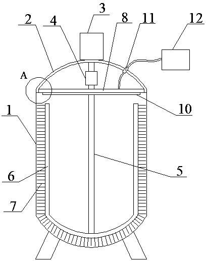
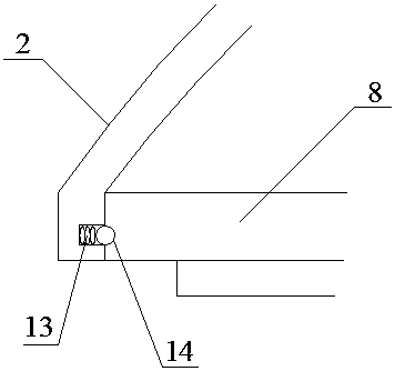
[0026] Such as figure 1 , image 3 , Figure 4 Shown, a kind of chemical reaction kettle dirt removal device, a kind of chemical reaction kettle dirt removal device, comprises reactor, and described reactor comprises kettle body 1 and kettle cover 2, and motor 3 is set on described kettle cover 2, and described The rotating shaft of the motor 3 is arranged on the inside of the kettle cover 2, the rotating shaft of the motor 3 is connected with the cleaning mechanism through a coupling 4, and the inside of the kettle cover 2 is provided with a spraying mechanism;
[0027] The decontamination mechanism includes a vertical rod 5 and a U-shaped rod 6 connected to the lower end of the vertical rod 5, the outer side of the U-shaped rod 6 is provided with bristles 7, and the spray mechanism includes a disc 8, and the disc 8 The center is provided with a through hole 9 for the vertical rod 5 to pass through, the bottom surface of the disc 8 is provided with a nozzle 10, and the kett...
Embodiment 2
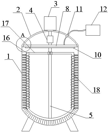
[0030] Such as Figure 2~4 Shown, a kind of chemical reaction kettle dirt removal device, a kind of chemical reaction kettle dirt removal device, comprises reactor, and described reactor comprises kettle body 1 and kettle cover 2, and motor 3 is set on described kettle cover 2, and described The rotating shaft of the motor 3 is arranged on the inside of the kettle cover 2, the rotating shaft of the motor 3 is connected with the cleaning mechanism through a coupling 4, and the inside of the kettle cover 2 is provided with a spraying mechanism;
[0031] The decontamination mechanism includes a vertical rod 5 and a U-shaped rod 6 connected to the lower end of the vertical rod 5, the outer side of the U-shaped rod 6 is provided with bristles 7, and the spray mechanism includes a disc 8, and the disc 8 The center is provided with a through hole 9 for the vertical rod 5 to pass through, the bottom surface of the disc 8 is provided with a nozzle 10, and the kettle cover 2 is provided...
Embodiment 3
[0038] Such as figure 1 , image 3 , Figure 4 Shown, a kind of chemical reaction kettle dirt removal device, a kind of chemical reaction kettle dirt removal device, comprises reactor, and described reactor comprises kettle body 1 and kettle cover 2, and motor 3 is set on described kettle cover 2, and described The rotating shaft of the motor 3 is arranged on the inside of the kettle cover 2, the rotating shaft of the motor 3 is connected with the cleaning mechanism through a coupling 4, and the inside of the kettle cover 2 is provided with a spraying mechanism;
[0039] The decontamination mechanism includes a vertical rod 5 and a U-shaped rod 6 connected to the lower end of the vertical rod 5, the outer side of the U-shaped rod 6 is provided with bristles 7, and the spray mechanism includes a disc 8, and the disc 8 The center is provided with a through hole 9 for the vertical rod 5 to pass through, the bottom surface of the disc 8 is provided with a nozzle 10, and the kett...
PUM
 Abstract
Description
Claims
Application Information
 - R&D
- Intellectual Property
- Life Sciences
- Materials
- Tech Scout
- Unparalleled Data Quality
- Higher Quality Content
- 60% Fewer Hallucinations
Browse by: Latest US Patents, China's latest patents, Technical Efficacy Thesaurus, Application Domain, Technology Topic, Popular Technical Reports.
© 2025 PatSnap. All rights reserved.Legal|Privacy policy|Modern Slavery Act Transparency Statement|Sitemap|About US| Contact US: help@patsnap.com


