
Comprehensive shear tester for anchoring bodies and test method thereof

A technology of experimental device and experimental method, which is applied in the direction of measuring device, using stable shear force to test the strength of materials, instruments, etc., can solve the problems of not being targeted, not too economical and convenient, and not very meaningful in application , to achieve reliable experimental results, reduce shear fracture, and novel structure

Pending Publication Date: 2019-01-01
HENAN POLYTECHNIC UNIV
View PDF10 Cites 10 Cited by
  • Summary
  • Abstract
  • Description
  • Claims
  • Application Information

AI Technical Summary

Problems solved by technology

However, the existing bolt shear research cannot simulate the actual stress on the bolt by the surrounding rock of the roadway, and the conclusions drawn may not have much significance for practical engineering applications. Although some experimental devices can simulate some actual engineering situation, but the function is single, the operation is inconvenient, and it is not targeted, so it is not very economical and convenient for practical application
Therefore, the development of a comprehensive simulation experiment device with a simple and reasonable structure that can simulate the force of the bolt can effectively solve the problems of time-consuming and labor-intensive and low accuracy of the existing technology, and can meet the double-shear simulation experiments of different types of bolts. , so as to effectively reduce the occurrence of bolt support failure, and also provide a scientific basis for geotechnical engineering such as water conservancy, tunnels, and mines

Method used


Image

  • Comprehensive shear tester for anchoring bodies and test method thereof

Examples


Embodiment Construction

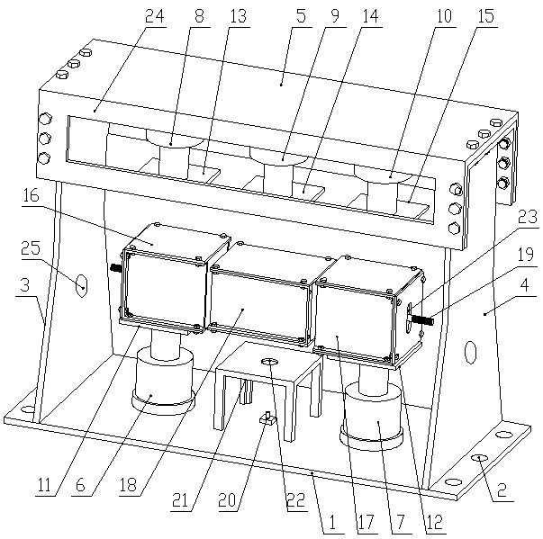
[0023] Such as figure 1 As shown, the comprehensive anchoring shear test device of the present invention includes a horizontally arranged base plate 1, the left and right sides of the base plate 1 are provided with anchor holes 2, and the base plate 1 is vertically arranged (welded) with a left vertical plate 3 and Right vertical plate 4, top plate 5 is arranged horizontally on the upper ends of left vertical plate 3 and right vertical plate 4, left jacking oil cylinder 6 and right jacking oil cylinder 7 are arranged on the upper surface of bottom plate 1, left lower pressing oil cylinder is fixedly arranged on the lower surface of top plate 5 8. The middle and lower pressure oil cylinder 9 and the right lower pressure oil cylinder 10, the left jacking oil cylinder 6 and the left lower pressure oil cylinder 8 are set up and down correspondingly, the right jacking oil cylinder 7 and the right down pressing oil cylinder 10 are set up and down correspondingly, and the telescoping ...


PUM


Abstract

The invention relates to a comprehensive shear tester for anchoring bodies, which comprises a bottom plate, a left vertical plate and a right vertical plate are arranged on the bottom plate, a top plate is arranged at the upper ends of the left vertical plate and the right vertical plate, a left jacking cylinder and a right jacking cylinder are arranged on the upper surface of the bottom plate, aleft pressing cylinder, a middle pressing cylinder and a right pressing cylinder are fixedly arranged on the lower surface of the top plate, a first test box is placed on the left jacking cylinder, asecond test box is placed on the right jacking cylinder, a third test box is arranged between the first test box and the second test box, and the interiors of the first test box, the second test box and the third test box are connected together in series through an anchor rod or an anchor cable. The invention further discloses a test method for the comprehensive shear tester for anchoring bodies.The comprehensive shear tester can be widely applied in the performance test of various anchor rods or anchor cables, and can accurately test the operating characteristics of the anchor rod or the anchor cable under the effect of shear, test results are reliable, the shear fracture of the anchor rods and the anchor cables in the process of production can be effectively reduced, and a scientific basis can be provided for mine supports and the like.

Description

technical field [0001] The invention belongs to the technical field of coal mine roadway support, and in particular relates to an anchor body comprehensive shearing experiment device and an experiment method thereof. Background technique [0002] Since the 1990s, bolt support has been widely used in coal mines due to its remarkable technical and economic advantages, and it is a revolution in roadway support. A large number of experts and scholars have done a lot of work in support theory, parameter design methods and effect monitoring, and have achieved many meaningful results. However, bolt support failure still occurs from time to time. Anchor shear failure has become the primary problem of anchor failure. Therefore, there must be sufficient research on the properties and structure of the roof rock formation and the anchoring characteristics of the bolt. However, the underground environment of coal mines is quite harsh, and it is difficult to obtain the above conditions...

Claims


Application Information

Patent Timeline
Patent Type & Authority Applications(China)
IPC IPC(8): G01N3/24
CPCG01N3/24G01N2203/0682G01N2203/0048G01N2203/0264
Inventor 刘少伟贾后省王伟尹文怀赵惠君姜彦军于涛付孟雄王永峰李小鹏许莉莉
Owner HENAN POLYTECHNIC UNIV
Learn More