Server common air guide cover structure
A technology of air guide cover and server, which is applied in the direction of instruments, electrical digital data processing, and digital data processing components, etc. It can solve the problems of inability to meet the heat dissipation requirements of servers, unfavorable server structure processing costs, and excessive server cost expenses, etc., to achieve structural Simple, concise structure, cost-optimized effect
- Summary
- Abstract
- Description
- Claims
- Application Information
AI Technical Summary
Problems solved by technology
Method used
Image
Examples
Embodiment 1
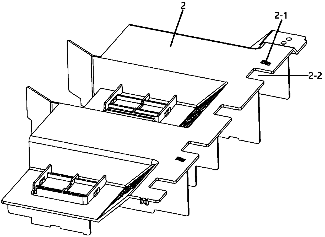
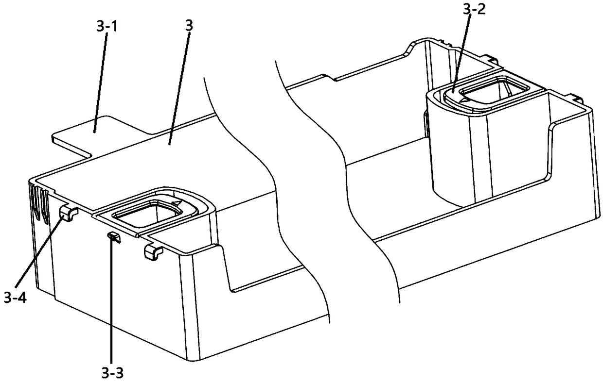
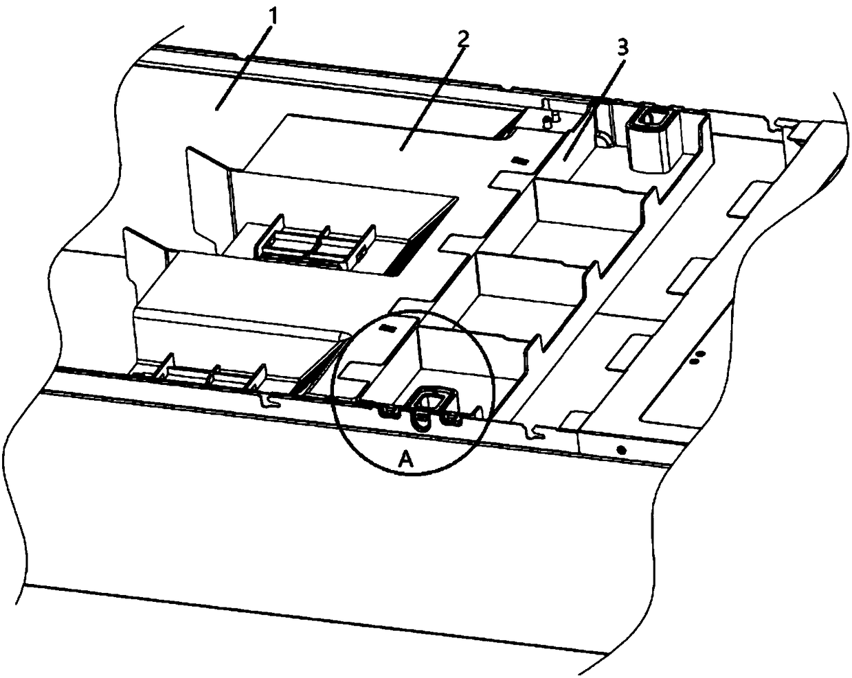
[0039] A common air duct structure for servers, such as figure 1 and 2 As shown, it includes a common wind guide 2 and an extension piece 3, the common wind guide 2 is arranged inside the chassis base 1 of the server, the common wind guide 2 is detachably connected to the chassis base 1, and the extension piece 3 is open on the upper end. In the box body, the extension piece 3 is arranged above the fan module, the extension piece 3 is connected to the air inlet end of the shared air guide cover 3 through the connecting piece, and the connecting piece is arranged at the upper end of the side wall of the extension piece 3 close to the shared air guide cover 2, The connecting piece is connected with the extension piece 3 .
[0040] Further, the air inlet end of the shared air guide 2 is provided with a common air guide gap 2-2, and the extension part 3 is provided with a convex plate 3-1 at an end close to the common air guide 2, and the convex plate 3-1 It is fixedly connected...
Embodiment 2
[0051] Present embodiment 2 is identical in structure with embodiment 1, as figure 2 As shown, the difference is that a limit hole 1-2 is also provided on the side wall of the chassis base 1, a limit structure 3-4 is provided on the side wall of the extension piece 3, and the limit structure 3-4 and the extension piece 3 The side walls are connected, the limiting structure 3-4 is a hook, the limiting structure 3-4 is made of plastic material, and the limiting structure 3-4 cooperates with the limiting hole 1-2.
[0052] Further, there are multiple limiting holes 1-2, and the limiting holes 1-2 are evenly distributed on both sides of the first fixing hole 1-1. This arrangement can improve the position-limiting effect, prevent the end of the extension piece 3 close to the common wind guide 2 and the end away from the common wind guide 2 from sinking or upturning, so that the extension 3 cannot be kept horizontal. Specifically, the front wall and the rear wall of the chassis ba...
Embodiment 3
[0057] Embodiment 3 has the same structure as Embodiment 1, the difference is that
[0058] Such as Figure 5 As shown, in the present embodiment 3, the side wall of the extension piece 3 is provided with a punched and formed bent plate 3-5, and the lower end of the bent plate 3-5 is connected with the extension piece 3, and the bent plate 3-5 is bent The left and right sides of the plate 3-5 have gaps with the side walls of the extension piece 3. The extension piece 3 and the bent plate 3-5 are designed in one piece, and the bent plate can move away from the side of the chassis base 1 around the bend line 3-7. Bending in the direction of the wall, the bending line 3-7 is the connection between the bending plate 3-5 and the extension piece 3, and the bending plate 3-5 is provided with a fixed structure 2 3-6 on the side close to the side wall of the chassis base 1 , the fixed structure 2 3-6 is connected with the bent plate 3-5, the side wall of the chassis base 1 is provided...
PUM
 Abstract
Description
Claims
Application Information
 - R&D
- Intellectual Property
- Life Sciences
- Materials
- Tech Scout
- Unparalleled Data Quality
- Higher Quality Content
- 60% Fewer Hallucinations
Browse by: Latest US Patents, China's latest patents, Technical Efficacy Thesaurus, Application Domain, Technology Topic, Popular Technical Reports.
© 2025 PatSnap. All rights reserved.Legal|Privacy policy|Modern Slavery Act Transparency Statement|Sitemap|About US| Contact US: help@patsnap.com


