Draw-bar box with antitheft function

A trolley case and functional technology, applied in luggage, clothing, accessories, etc., can solve the problems of not being able to place things, cannot be fixed, and does not have anti-theft, etc., and achieve the effect of increasing the function of placing things, stable structure, and convenient use

Inactive Publication Date: 2019-01-04
潘素娇
View PDF0 Cites 0 Cited by
  • Summary
  • Abstract
  • Description
  • Claims
  • Application Information

AI Technical Summary

Problems solved by technology

[0003] The existing trolley case has a relatively simple structure and relatively few functions. When in use, the trolley case is easy to slide and break, does not have the function of preventing sliding, and cannot be fixed on uneven ground, which is inconvenient to use and does not have the function of anti-theft. Unreasonable, generally things are placed on the upper end of the trolley case, but some small items such as cups cannot be placed, and do not have the function of placing things

Method used


Image

  • Draw-bar box with antitheft function
  • Draw-bar box with antitheft function
  • Draw-bar box with antitheft function

Examples


Embodiment 1

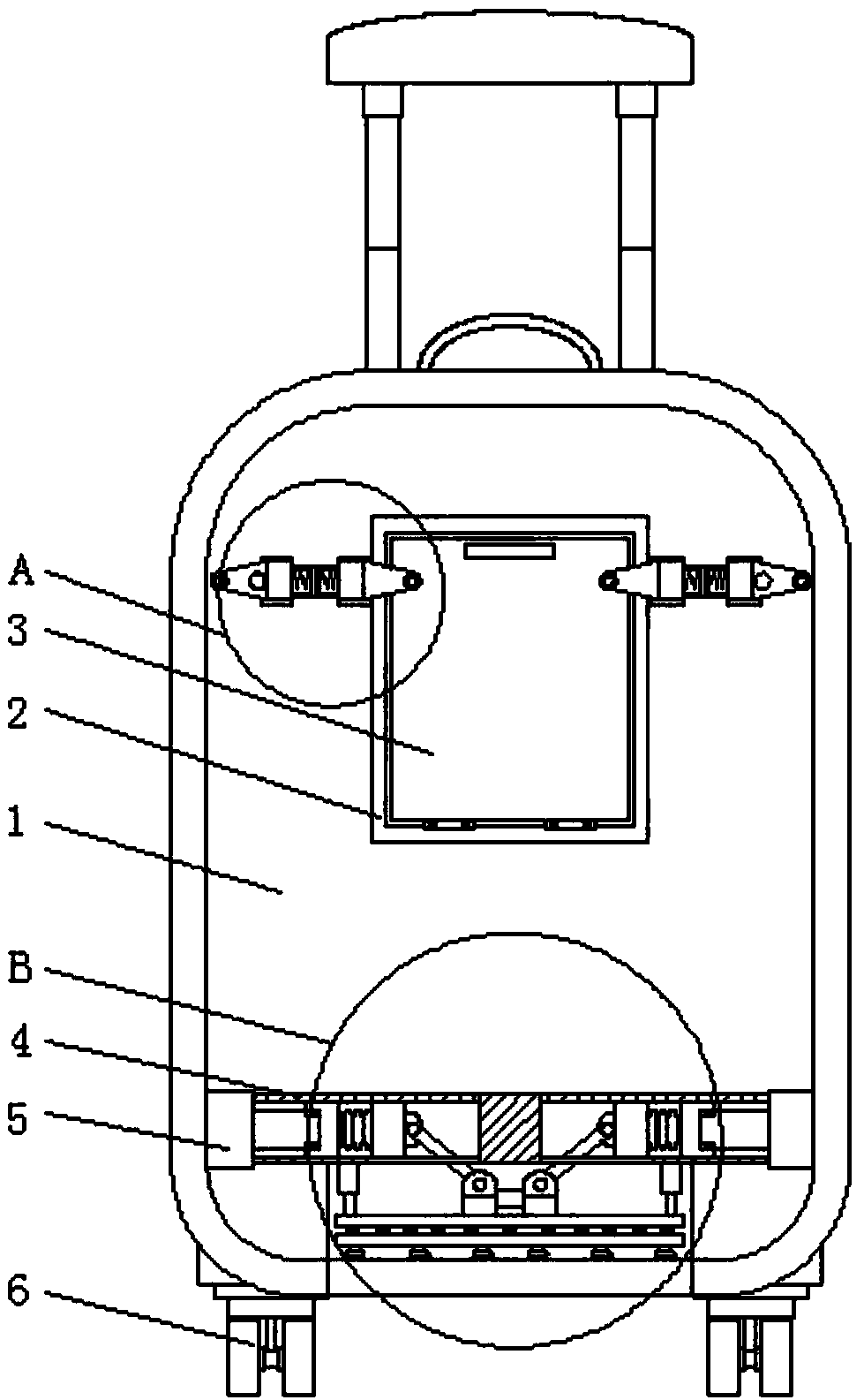
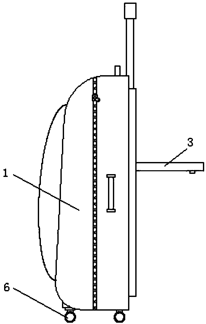
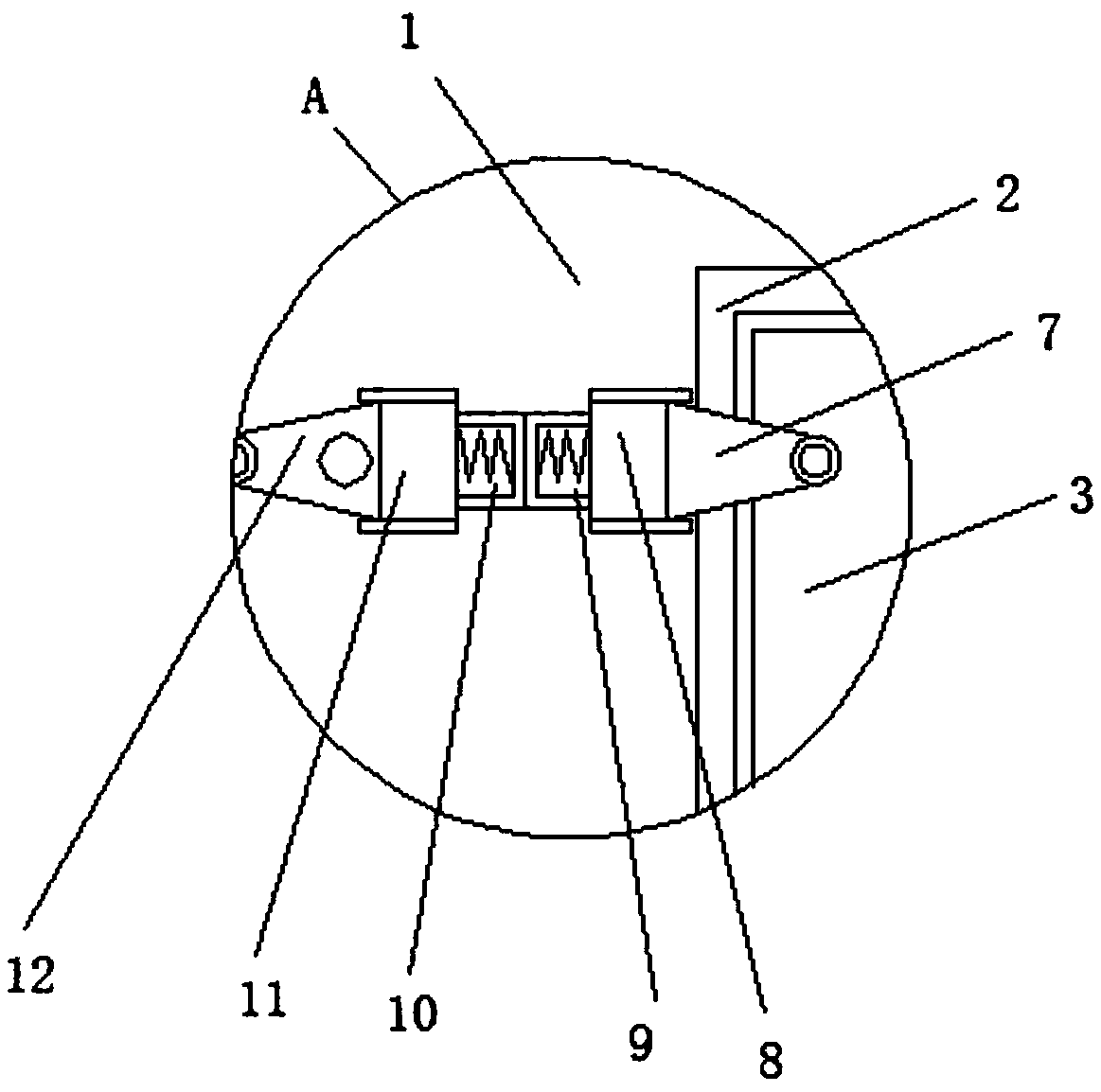
[0024] refer to figure 1 , figure 2 , image 3 , Figure 4 , a trolley case with anti-theft function, comprising a case body 1, the bottom position of the case body 1 is provided with a moving wheel 6, the inner bottom position of the case body 1 is fixedly connected with an operating room 4, and the inner side wall of the case body 1 is provided with a motorized Push rod 5, the interior of operating room 4 is provided with push block A13 and push block B15, between push block A13 and push block B15 fixedly connected by connection spring 14, one end of electric push rod 5 is fixedly connected with push block A13, push block One side wall of B15 is rotatably connected with a support rod 21, the lower end of the support rod 21 is rotatably connected with a column 20, and the lower end of the column 20 is fixedly connected with an upper horizontal plate 16, and the lower surface of the upper horizontal plate 16 is fixed by a plurality of buffer springs 17 A lower horizontal p...

Embodiment 2

[0027] refer to figure 1 , image 3 , Figure 4 , Figure 5 , a trolley case with anti-theft function, the upper surface of the placement plate 3 is provided with a chute C23, the inside of the chute C23 is slidably connected with a sliding ball 24, the upper end of the sliding ball 24 is provided with a reinforcing rod 25, the side of the placement plate 3 A handle is fixedly connected to the side of the wall away from the box body 1 .

[0028] Working principle: When in use, start the electric push rod 5, and the electric push rod 5 pushes the push block B15 through the push block A13 and the connecting spring 14, so that the support rods 21 are close to each other, and the upper horizontal plate 16 and the lower horizontal plate 18 are connected through the column 20 Push out the inside of the box body 1, the fixed suction cup 19 is in contact with the ground, and the buffer spring 17 makes the fixed suction cup 19 fix the box body 1 firmly even on uneven ground, avoidin...


PUM


Abstract

The invention discloses a draw-bar box with an antitheft function. The draw-bar box comprises a box body, movable wheels are arranged at the bottom of the box body, an operation chamber is fixedly connected at the inner bottom of the box body, an electric pushing rod is arranged on the inner side wall of the box body, a pushing block A and a pushing block B are arranged in the operation chamber and fixedly connected through a connecting spring, one end of the electric pushing rod is fixedly connected with the pushing block A, a supporting rod is rotatably connected on one side wall of the pushing block B, a vertical column is rotatably connected at the lower end of the supporting rod, an upper cross plate is fixedly connected at the lower end of the vertical column, the lower surface of the upper cross plate is fixedly connected with a lower cross plate through a plurality of buffer springs, a plurality of fixed suckers are uniformly and fixedly connected on the lower surface of the lower cross plate, a square groove is formed in one side of the box body, and a placing plate is hinged in the square groove. The draw-bar box has antitheft, antiskid and article placing functions.

Description

technical field [0001] The invention relates to the technical field of trolley cases, in particular to a trolley case with an anti-theft function. Background technique [0002] The trolley case refers to a suitcase with a trolley and a roller. The trolley inside the trolley case is divided into a single-tube trolley and a double-tube trolley. User burden, therefore widely used. [0003] The existing trolley case has a relatively simple structure and relatively few functions. When in use, the trolley case is easy to slide and break, does not have the function of preventing sliding, and cannot be fixed on uneven ground, which is inconvenient to use and does not have the function of anti-theft. Unreasonable, generally things are placed on the upper end of the trolley case, but some small items such as cups cannot be placed, and do not have the function of placing things. Contents of the invention [0004] The object of the present invention is to propose a trolley case with...

Claims


Application Information

Patent Timeline
Patent Type & Authority Applications(China)
IPC IPC(8): A45C5/04A45C5/14A45C13/18A45C13/26
CPCA45C5/045A45C5/14A45C13/18A45C13/262
Inventor 潘素娇
Owner 潘素娇
Why Eureka
Try Eureka