
In-situ remediation system for contaminated site

An in-situ repair and site technology, applied in the field of in-situ repair systems for polluted sites, can solve problems such as a large amount of electrical energy, limited power, and lag in the detection of repair effects, and achieve the effect of increasing the efficiency of thermal energy use and ensuring the repair effect.

Active Publication Date: 2019-01-04
山东冽泉环保工程咨询有限公司
View PDF10 Cites 6 Cited by
  • Summary
  • Abstract
  • Description
  • Claims
  • Application Information

AI Technical Summary

Problems solved by technology

[0004] At present, there are very limited cases of in-situ thermal desorption technology used in remediation projects of polluted sites, mainly because in-situ thermal remediation generally needs to set up vertical curtains on the pollution source area, and the ground needs to be hardened to prevent pollutants from being removed from the soil when the soil is heated. Ground escape causes secondary pollution. At the same time, the currently used ERH and TCH technologies need to set up a large number of heating wells, and invest a lot of electric energy or fuel consumption. Another disadvantage of TCH and ERH technologies is the comparison between adjustment and control during the restoration period. Difficulty, detection lag of repair effects
In addition, the currently used in-situ thermal desorption remediation technology requires a very high investment cost for the polluted site with deep pollution depth, and the engineering construction is also very difficult

Method used


Image

  • In-situ remediation system for contaminated site
  • In-situ remediation system for contaminated site
  • In-situ remediation system for contaminated site

Examples


Embodiment Construction

[0029] In order to make the purpose, technical solutions and advantages of the present invention clearer, the present invention will be further described in detail below in conjunction with the accompanying drawings. Obviously, the described embodiments are only some of the embodiments of the present invention, rather than all of them. Based on the embodiments of the present invention, all other embodiments obtained by persons of ordinary skill in the art without making creative efforts belong to the protection scope of the present invention.

[0030] Terms used in the embodiments of the present invention are only for the purpose of describing specific embodiments, and are not intended to limit the present invention. The singular forms "a", "said" and "the" used in the embodiments of the present invention and the appended claims are also intended to include plural forms, unless the context clearly indicates otherwise, "multiple" Generally contain at least two.

[0031] It sho...


PUM


Abstract

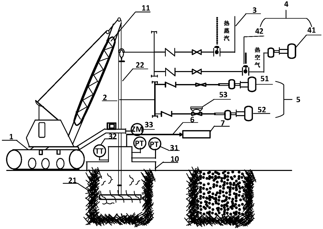
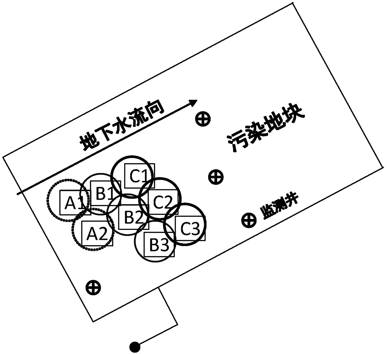
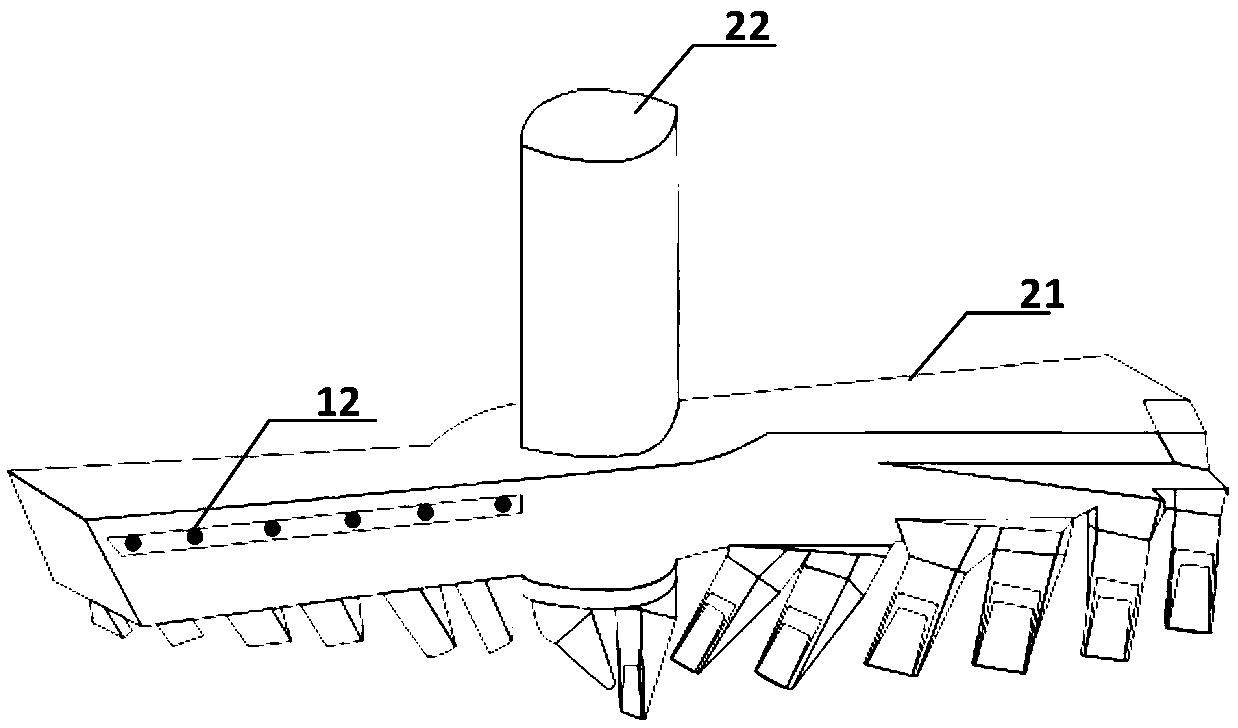
The invention provides an in-situ remediation system for a contaminated site. The in-situ remediation system comprises a moving platform (1), a drill bit system (2), a hot steam injection system (3),a hot air injection system (4) and a chemical injection system (5) and is characterized in that the moving platform comprises a rigid support (11) and controls the drill bit system to move verticallythrough the support of the rigid support; the drill bit system comprises a drill bit (21) and a hollow rod (22) extending upwardly along the drill bit (21); the hot steam injection system (3) is started first to inject hot steam in an in-situ manner to heat soil, then the hot air injection system (4) is started to inject hot air to enhance organic pollutant volatilization towards the ground, the hot steam injection and the hot air injection are stopped when remediation reaches a preset degree, and the chemical injection system (5) is started to inject chemicals during the stirring of the drillbit system (2). The in-situ remediation system has the advantages that various process parameters can be flexibly and conveniently regulated, and the complex contaminated site can be efficiently remediated in an energy-saving manner.

Description

technical field [0001] The invention relates to the field of environmental technology, in particular to an in-situ remediation system for polluted sites. Background technique [0002] After more than 30 years of rapid industrial development, a large amount of pollutants have entered the soil and groundwater through solid waste stacking and dumping, sewage leakage, atmospheric deposition, etc., resulting in a large number of chemically polluted plots. A large number of these chemically polluted plots have been included in the scope of redevelopment and utilization along with the planning of urbanization development. The pollution depth of some chemically polluted plots is relatively deep, reaching below 15 meters below the ground, so it is no longer suitable for restoration by excavation-treatment methods. A large number of in-situ remediation technologies have been used in deep-polluted plots, such as in-situ oxidation technology, multiphase extraction technology, air aerat...

Claims


Application Information

Patent Timeline
Patent Type & Authority Applications(China)
IPC IPC(8): B09C1/06B09C1/08B09C1/10
CPCB09C1/06B09C1/08B09C1/10B09C2101/00
Inventor 李静郭观林李文志
Owner 山东冽泉环保工程咨询有限公司
Learn More