Flow restrictor in micro-droplet jetting printing head

A technology of droplet jetting and jet printing, which is applied in the field of restrictors, can solve problems such as pressure loss in the pressure chamber and pressure crosstalk in the pressure chamber, and achieve the effect of reducing pressure loss, reducing pressure crosstalk, and being easy to implement

Pending Publication Date: 2019-01-04
NAT INST CORP OF ADDITIVE MFG XIAN
View PDF8 Cites 3 Cited by
  • Summary
  • Abstract
  • Description
  • Claims
  • Application Information

AI Technical Summary

Problems solved by technology

[0007] In order to solve the technical problem that the current limiter of the existing droplet jet printing head is likely to cause the pressure loss of the pressure chamber and the pressure crosstalk between the pressure chambers, the present invention provides a current limiter of the droplet jetting print head

Method used


Image

  • Flow restrictor in micro-droplet jetting printing head
  • Flow restrictor in micro-droplet jetting printing head
  • Flow restrictor in micro-droplet jetting printing head

Examples


Embodiment Construction

[0036] The purpose of the present invention is to construct a flow restrictor structure that is easy to process, and can effectively reduce the backflow of liquid in the pressure chamber and the pressure crosstalk between the pressure chambers, so as to improve the performance of the print head. The present invention will be described in detail below in conjunction with the accompanying drawings.

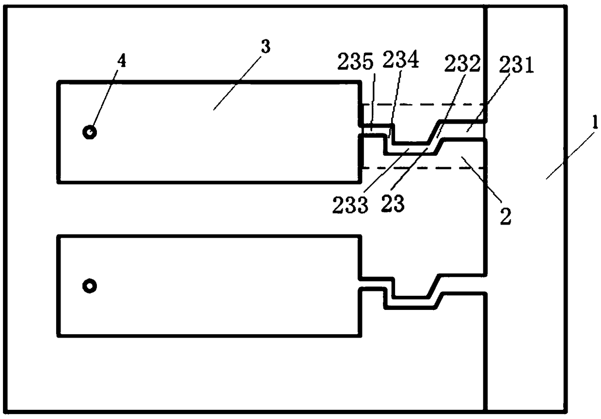
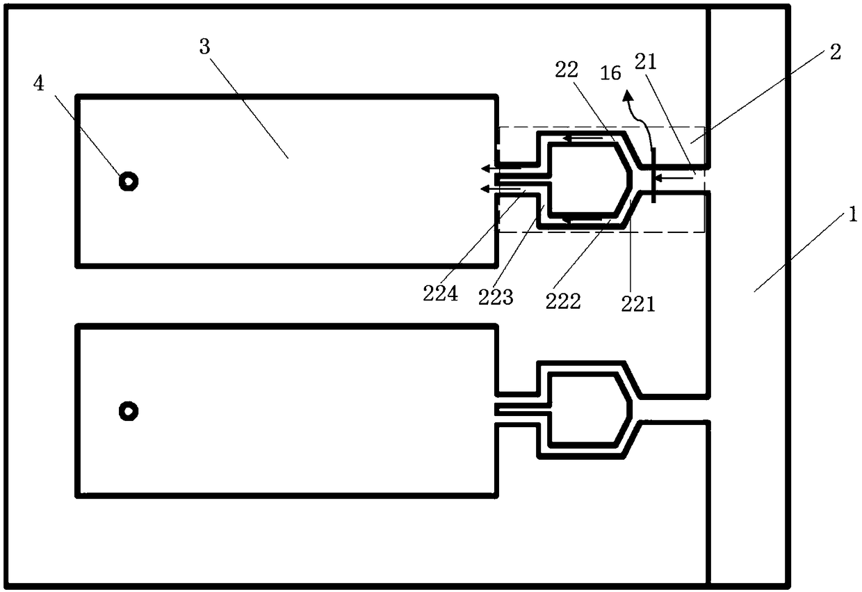
[0037] Such as Figure 2-3 As shown, the droplet jet printing head includes a main ink channel 1 , a flow restrictor 2 , an orifice 4 and a pressure chamber 3 . The main ink channel 1 is filled with the ink to be ejected; one end of the restrictor 2 is connected with the main ink channel 1 , and the other end is connected with the pressure chamber 3 . Pressure waves are generated in the pressure chamber 3 due to deformation and vibration of the piezoelectric body. The nozzle hole 4 is a droplet ejection outlet. When working, the ink flows from the main ink channel 1 through the f...


PUM


Abstract

The invention relates to a flow restrictor in a micro-droplet jetting printing head in order to solve a technical problem that the existing flow restrictor of the micro-droplet jetting printing head is liable to cause pressure loss of a pressure chamber and pressure crosstalk between the pressure chambers. The first flow restrictor provided by the invention comprises a main ink path and multiple branch ink paths arranged at the outlet of the main ink path in parallel, wherein the branch ink paths are zigzag ink paths, and the central axis of each zigzag ink path is a broken line. Meanwhile, the invention further provides a flow restrictor with another structure. The flow restrictor comprises an ink path, wherein the ink path is a zigzag ink path or a section of the ink path is a zigzag inkpath, and the central axis of the zigzag ink path is a broken line. The flow restrictor adopts the zigzag ink path, and the zigzag ink path is conducive to increasing the flow damping at the outlet of the pressure chamber, reducing the backflow of a liquid in the pressure chamber, reducing the pressure loss in the pressure chamber and improving the jetting performance of the printing head and capable of reducing the pressure crosstalk between the pressure chambers at the same time.

Description

technical field [0001] The invention belongs to the field of droplet ejection, and relates to a current limiter in a droplet ejection print head. Background technique [0002] Most of the droplet jet printing technology uses a certain extrusion method to create a pressure difference between the ink chamber and the outside world, so that the pressure inside the nozzle is greater than the pressure outside the nozzle, so that the ink is pushed out of the nozzle to form a printing technology of tiny ink droplets. The current typical droplet jet printing technology is divided into two categories, namely continuous inkjet technology and drop-on-demand inkjet technology. The drop-on-demand inkjet technology is widely used because of its simple structure and precise control of droplet ejection on demand. [0003] At present, there are two mainstream on-demand printing technologies: one is the thermal bubble inkjet print head, and its working principle is to use the expansion force ...

Claims


Application Information

Patent Timeline
Patent Type & Authority Applications(China)
IPC IPC(8): B41J2/14
CPCB41J2/14
Inventor 王莉原瑞凝黄菲卢秉恒赵纪元
Owner NAT INST CORP OF ADDITIVE MFG XIAN
Why Eureka
Try Eureka