Accidental injury prevention shield used for unmanned aerial vehicle

An unmanned aerial vehicle (UAV) and anti-error technology, applied in the field of UAV, can solve problems such as unfavorable stable flight of UAV, and achieve the effect of high safety, good intelligence and light equipment.

Inactive Publication Date: 2019-01-04
郑州谓凡智能科技有限公司
0 Cites 2 Cited by

AI-Extracted Technical Summary

Problems solved by technology

When recycled, it can land automatically and can be used repeatedly. Among them, plant protection drones are widely used in agricultural-related tasks such as pesticide spraying, pollination, and sowing. Parts that are easy to be damaged. So...

Method used

Bottom strut 15 inboards are provided with motor support 8, and motor support 8 is connected to bottom strut 15 by screw, and motor support 8 one side is provided with block 9, and block 9 and motor support 8 are integrally formed, and block 9 The lower end is provided with a buckle 10, the block 9 is connected to the buckle 10 by a buckle, the bottom strut 15 plays a supporting role at the bottom, and the motor support 8 is connected with the bottom strut...

Abstract

The invention discloses an accidental injury prevention shield used for an unmanned aerial vehicle. The accidental injury prevention shield comprises an unmanned aerial vehicle main machine, a first protection cover, a support rod and a wireless communicator, wherein the support rod is arranged on one side of the unmanned aerial vehicle main machine; an overturning motor is arranged between the unmanned aerial vehicle main machine and the support rod; the overturning motor is connected onto the unmanned aerial vehicle main machine through bolts; the overturning motor is connected to the support rod through screws; a fourth protection cover is arranged on one side of the support rod; a first protection cover is arranged on the rear side of the fourth protection cover; and a second protection cover is arranged on one side of the first protection cover. The accidental injury prevention shield has the beneficial effects that the safety is high, the upper and lower protection covers are arranged, an innocent person cannot be hurt when the equipment operates, the intelligence is high, an arranged infrared sensor can respond in time under the condition of no human-machine space-time, theequipment is light, the whole body is made from a synthetic material, and the load influence on the unmanned aerial vehicle after the unmanned aerial vehicle is mounted is little.

Application Domain

Technology Topic

EngineeringSynthetic materials +2

Image

  • Accidental injury prevention shield used for unmanned aerial vehicle
  • Accidental injury prevention shield used for unmanned aerial vehicle
  • Accidental injury prevention shield used for unmanned aerial vehicle

Examples

  • Experimental program(3)

Example Embodiment

[0034] Example 1
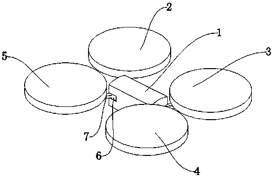
[0035] Such as Figure 1-Figure 6 As shown, an anti-injury protective cover for drones includes a drone host 1, a first protective cover 2, a support rod 7, and a wireless communicator 23. A support rod 7 is provided on one side of the drone host 1 for wireless communication. The device 23 plays a communication role, and the support rod 7 plays a supporting role. A turning motor 6 is arranged between the drone host 1 and the support rod 7, and the turning motor 6 plays an adjustment role. The turning motor 6 is connected to the drone host 1 by bolts. The drone host 1 plays a bearing role, and the turning motor 6 is connected to the support rod 7 by screws. The support rod 7 is provided with a fourth protective cover 5 on one side, the fourth protective cover 5 plays a protective role, and the fourth protective cover 5 is provided on the rear side There is a first protective cover 2, the first protective cover 2 plays a protective role, the first protective cover 2 is provided with a second protective cover 3 on one side, the second protective cover 3 plays a protective role, and the second protective cover 3 is provided with a first Three protective covers 4, the third protective cover 4 plays a protective role, the first protective cover 2 includes an upper protective net 17, a bottom protective net 22, a support ring 12, the upper protective net 17 is provided with a fixing block 13 outside the upper protective net 17 For protection, the fixed block 13 plays a fixed role, the fixed block 13 is provided with a connecting block 16 on one side, the connecting block 16 plays a connecting role, and the outer side of the connecting block 16 is provided with an upper lock ring 11, which plays a locking role, and the fixed block 13 Connect with the upper lock ring 11 by gluing, and the connecting block 16 is connected with the upper lock ring 11 by gluing. A support ring 12 is provided at the lower end of the upper lock ring 11. The support ring 12 plays a supporting role. The upper lock ring 11 is glued and supported. The ring 12 is connected. The lower end of the support ring 12 is provided with a bottom brace 15 which plays a supporting role. The bottom brace 15 is connected to the support ring 12 by gluing. The bottom brace 15 is provided with a bottom guard net 22 at the lower end. The net 22 plays a protective role, and the bottom guard net 22 is connected to the bottom brace 15 through a buckle.

Example Embodiment

[0036] Example 2
[0037] The difference between this embodiment and embodiment 1 is:
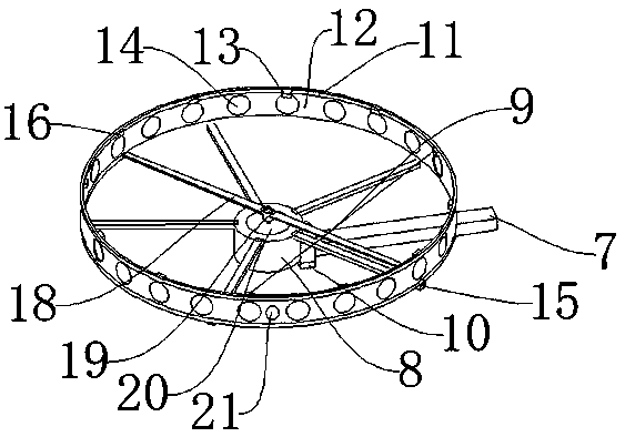
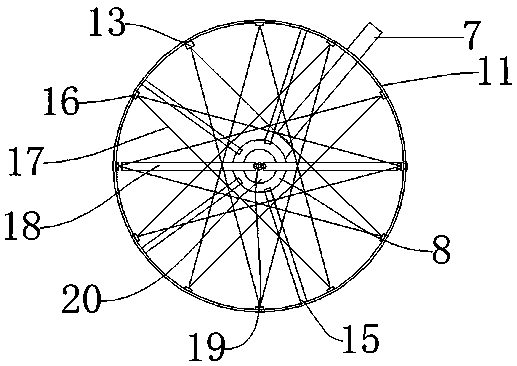
[0038] The inner side of the bottom brace 15 is provided with a motor bracket 8, which is connected to the bottom brace 15 by screws. A clamping block 9 is provided on one side of the motor bracket 8. The clamping block 9 and the motor bracket 8 are integrally formed, and the lower end of the clamping block 9 is provided with The lock 10 and the clip 9 are connected to the lock 10 by a clip, the bottom brace 15 supports the bottom, and the motor bracket 8 is connected to the bottom brace 15 by screws to ensure the stability of the motor bracket 8.

Example Embodiment

[0039] Example 3
[0040] The difference between this embodiment and embodiment 1 is:
[0041] The inner side of the motor support 8 is provided with a screw motor 20, which is connected to the motor support 8 by a buckle, a fan blade support 19 is provided on the upper end of the screw motor 20, and the fan blade support 19 is connected to the screw motor 20 by a key. The buckle is connected to the motor bracket 8, which facilitates unmanned installation and disassembly.
[0042] Working principle: first use the clamping block 9 to clamp on the support rod 7, and lock the lock 10, then the bottom support rod 15 is stuck on the support rod 7, and then the screw motor 20, the fan blade bracket 19, and the screw The fan blade 18 is installed, and then the support ring 12 and the upper lock ring 11 are clamped on the bottom strut 15 and the upper guard net 17 is installed. The equipment is installed completely. During the flight, the infrared sensor 21 detects the surrounding environment in real time. 21 When a living object is detected, a signal is sent to the processor 26, the processor 26 controls the controller 24, and the controller 24 controls the screw motor 20 to stay away from the living object.

PUM

no PUM

Description & Claims & Application Information

We can also present the details of the Description, Claims and Application information to help users get a comprehensive understanding of the technical details of the patent, such as background art, summary of invention, brief description of drawings, description of embodiments, and other original content. On the other hand, users can also determine the specific scope of protection of the technology through the list of claims; as well as understand the changes in the life cycle of the technology with the presentation of the patent timeline. Login to view more.

Similar technology patents

Classification and recommendation of technical efficacy words

  • Improve security
  • Smart

Method and system for powerline networking

InactiveUS20060018328A1Improve securityEasy to changeBroadband local area networksBroadcast transmission systemsComputer network
Owner:COMCAST CABLE COMM LLC

Intelligent positioning and door opening control system and control method thereof

InactiveCN107067518AEasy and accurate location lookupSmartIndividual entry/exit registersEmbedded systemSmart phone
Owner:重庆小火柴智能科技有限公司

Component management method and device and mobile terminal

InactiveCN107944266AAvoid allocation errorsSmartPlatform integrity maintainanceProgram loading/initiatingApproaches of managementThe Internet
Owner:BEIJING QIHOO TECH CO LTD

Battling mode switching method and device, storage medium and terminal

InactiveCN108096840AGood experienceSmartVideo gamesSufficient timeMode switching
Owner:TENCENT TECH (SHENZHEN) CO LTD
Why Eureka
Try Eureka