Lifting device for building material transportation

A technology for buildings and adjustment boxes, applied in the direction of hoisting devices, clockwork mechanisms, etc., can solve problems such as affecting construction efficiency and reliability, limited use, inflexibility, etc., to achieve diversified improvement effects, stable transmission, The effect of improving conveying efficiency

Active Publication Date: 2019-01-04
河南省建筑设计研究院有限公司
View PDF7 Cites 0 Cited by
  • Summary
  • Abstract
  • Description
  • Claims
  • Application Information

AI Technical Summary

Problems solved by technology

[0009] Aiming at the deficiencies of the prior art, the present invention provides a lifting device for building material transportation, which solves the problem that the existing building material lifting device is complex in structure, very limited in use, not flexible enough, and affects construction efficiency and low reliability. technical problem

Method used


Image

  • Lifting device for building material transportation
  • Lifting device for building material transportation
  • Lifting device for building material transportation

Examples


Embodiment 1

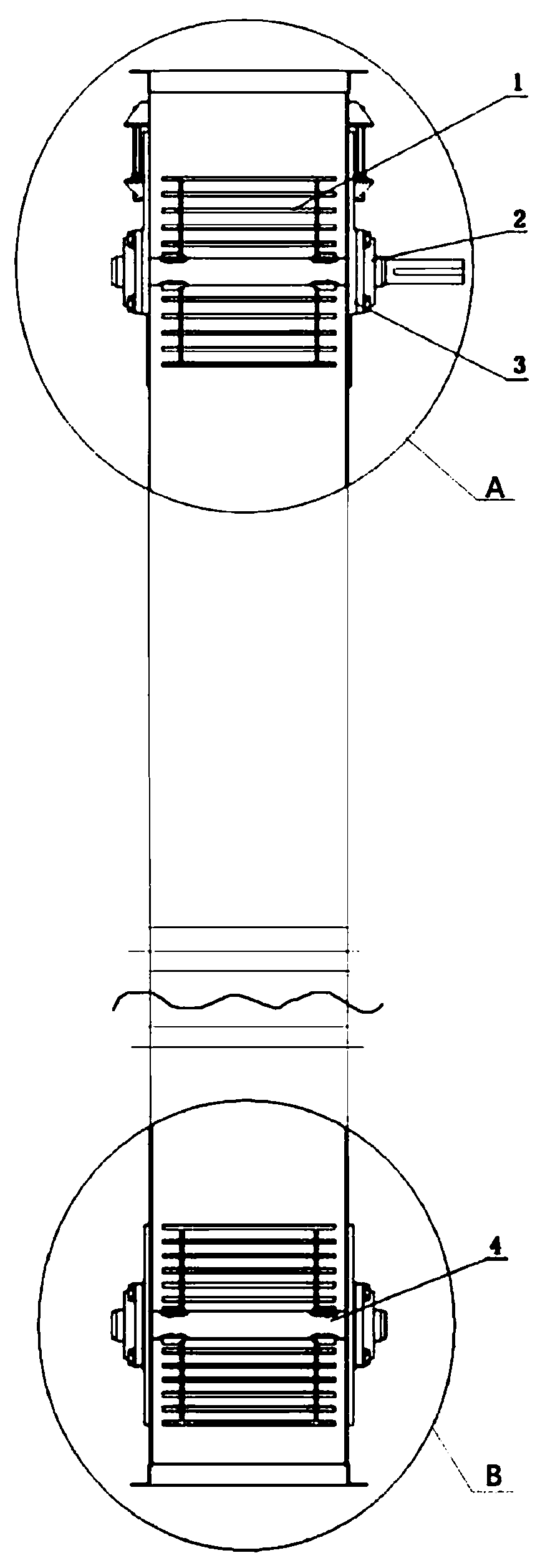
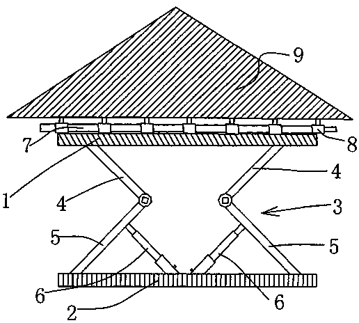
[0050] see Figure 3-7 , a lifting device for transporting building materials, comprising: a base 1, a support column 2, a fixing seat 3, and an adjustment box 4; both ends of the base 1 are provided with first grooves 11, and the first grooves One side of 11 is provided with limiting groove 12; One side of support column 2 is provided with second groove 27, and second groove 27 is provided with screw mandrel 21; Both ends of holder 3 are fixedly connected with transmission block 31, Both sides of the top of the fixing seat 3 are fixedly connected with fixing heads 32;

[0051] Both sides of the top of the base 1 are fixedly connected with a support block 13, one side of the support block 13 is provided with a first transmission shaft 14, one end of the first transmission shaft 14 is flexibly connected with the support block 13, and the other end of the first transmission shaft 14 One end is inserted into the first groove 11 and is fixedly connected with the first bevel gear ...

Embodiment 2

[0064] A lifting device for transporting building materials, comprising: a base 1 , a supporting column 2 , a fixing seat 3 , and an adjusting box 4 .

[0065] Both ends of the interior of the base 1 are provided with a first groove 11, one side of the first groove 11 is provided with a limiting groove 12, and both sides of the top of the base 1 are fixedly connected with a support block 13, one of the support blocks 13 The side is provided with a first transmission shaft 14, one end of the first transmission shaft 14 is flexibly connected with the support block 13, the other end of the first transmission shaft 14 is inserted into the first groove 11 and is fixedly connected with the first bevel gear 16, the first A first winding wheel 15 is fixedly connected to the outside of the middle part of the transmission shaft 14 .

[0066] One side of the support column 2 is provided with a second groove 27, the second groove 27 is provided with a screw rod 21, one end of the screw ro...


PUM


Abstract

The invention discloses a lifting device for building material transportation. The lifting device comprises a base; first grooves are formed in two ends in the base; limiting grooves are formed in onesides of the first grooves; support blocks are fixedly connected to two sides of the top end of the base; first transmission shafts are arranged on one sides of the support blocks; and one ends of the first transmission shafts are movably connected with the support blocks. Through cooperative arrangement among steel wire ropes, winding wheels and the transmission shafts, the lifting device for building material transportation can quickly lift materials, improves the working efficiency, and is suitable for lighter materials; through cooperative arrangement of lead screws and transmission blocks, the lifting device can slowly and stably lift the materials, guarantees the stability, and is suitable for heavier materials; through arrangement of adjusting boxes, two sets of lifting methods areconveniently converted; and through arrangement of rotating discs, the conveying direction and position are conveniently adjusted, and the conveying efficiency is improved.

Description

technical field [0001] The invention belongs to the technical field of building material transportation equipment, in particular to a lifting device for building material transportation. Background technique [0002] On the construction site, as the building continues to increase during the construction process, it is necessary to lift the building materials to the required height for construction. The material lifting device is a simple and convenient lifting device commonly used in building construction to solve vertical transportation. Electric hoist, steel wire rope, cable wind rope (attached to the wall frame), ground anchor and various safety protection devices, etc. [0003] The material hoist has the characteristics of simple structure, reliable technical performance, high safety factor, convenient disassembly and assembly, and ready-to-use, which can save a lot of labor. In the prior art, the commonly used material lifting devices are as follows: [0004] Chinese...

Claims


Application Information

Patent Timeline
Patent Type & Authority Applications(China)
IPC IPC(8): B66D1/12B66D1/14B66D1/28
CPCB66D1/12B66D1/14B66D1/28
Inventor 陈鹏胡殿彦龙玉辉余永奇张红亮安杰段朝辉李翔张向阳耿春
Owner 河南省建筑设计研究院有限公司
Why Eureka
Try Eureka