Eureka AIR delivers breakthrough ideas for toughest innovation challenges, trusted by R&D personnel around the world.

Hoist hydraulic control system and crane

A hydraulic control system and oil pressure control technology, which is applied in the hoist hydraulic control system and crane field, can solve problems such as insufficient construction, hydraulic shock, and endangering hoisting safety, so as to improve stability, prevent hydraulic shock, and improve the use of hoisting The effect of longevity

Active Publication Date: 2021-02-05
SANY AUTOMOBILE HOISTING MACHINERY
View PDF10 Cites 0 Cited by
  • Summary
  • Abstract
  • Description
  • Claims
  • Application Information

AI Technical Summary

Problems solved by technology

[0004] The disadvantage of this is that when the heavy object is stopped in mid-air, the brake of the reducer bears the load force. Due to the leakage of the hoist hydraulic motor, the closed cavity between the hoist hydraulic motor and the balance valve is not established enough. Therefore, during the secondary action (lifting or lowering) of the winch, when the brake is opened, the load force is quickly transmitted from the brake to the hydraulic motor, and the closed cavity between the hydraulic motor and the balance valve must be established Only by maintaining the load pressure can the load be supported. At this time, due to the leakage of the hydraulic motor, the compressibility of the oil, the gap between the hydraulic motor and the reducer, and the backlash of the internal gears of the reducer, the hydraulic shock of the hydraulic motor occurs , the sliding hook reverses, the brake produces sliding friction, mechanical collision occurs between the inner teeth of the reducer with noise, and the weight will sink slightly
This kind of problem directly affects the service life of the brake and reducer, the stability of the winch hoisting, and the customer's operating experience, especially in the heavy-duty hoisting condition, which seriously endangers the hoisting safety and has become one of the technical problems in the industry.

Method used


Image

  • Hoist hydraulic control system and crane
  • Hoist hydraulic control system and crane
  • Hoist hydraulic control system and crane

Examples


Embodiment 1

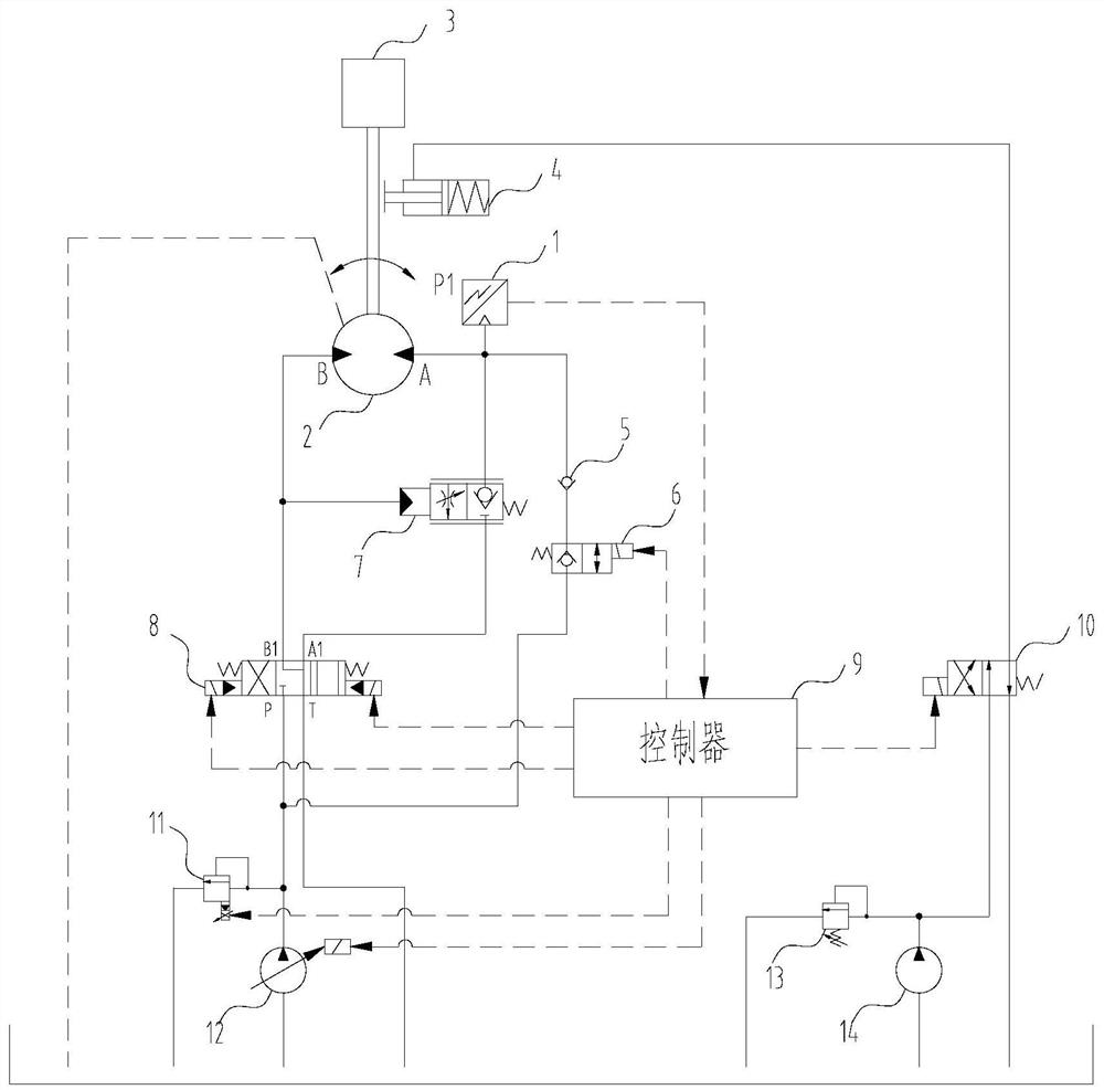
[0047] This embodiment provides a winch hydraulic control system, please refer to figure 1 , this winch hydraulic control system includes:

[0048] The winch hydraulic motor 2 is provided with a first oil port for controlling lifting and a second oil port for controlling lowering;

[0049] The brake 4, the brake 4 can selectively abut against the output shaft of the winch hydraulic motor 2, so as to control the brake of the winch hydraulic motor 2;

[0050] The main oil pump 12, the main oil pump 12 is connected with the hoist hydraulic motor 2, so as to supply oil to the hoist hydraulic motor 2;

[0051] The first reversing valve 8, the first reversing valve 8 is arranged between the hoist hydraulic motor 2 and the main oil pump 12, the first reversing valve 8 is used to control the communication between the main oil pump 12 and the first oil port or the second oil port ;

[0052] A balance valve 7, the balance valve 7 is arranged between the first oil port and the second ...

Embodiment 2

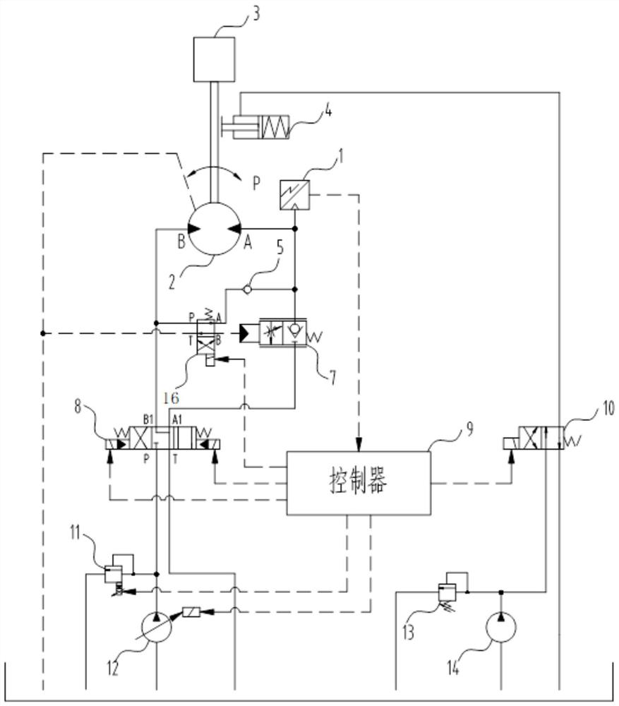
[0075] This embodiment provides a winch hydraulic control system, please refer to figure 2 , this winch hydraulic control system includes:

[0076] The winch hydraulic motor 2 is provided with a first oil port for controlling lifting and a second oil port for controlling lowering;

[0077] The brake 4, the brake 4 can selectively abut against the output shaft of the winch hydraulic motor 2, so as to control the brake of the winch hydraulic motor 2;

[0078] The main oil pump 12, the main oil pump 12 is connected with the hoist hydraulic motor 2, so as to supply oil to the hoist hydraulic motor 2;

[0079] The first reversing valve 8, the first reversing valve 8 is arranged between the hoist hydraulic motor 2 and the main oil pump 12, the first reversing valve 8 is used to control the communication between the main oil pump 12 and the first oil port or the second oil port ;

[0080] A balance valve 7, the balance valve 7 is arranged between the first oil port and the second...

Embodiment 3

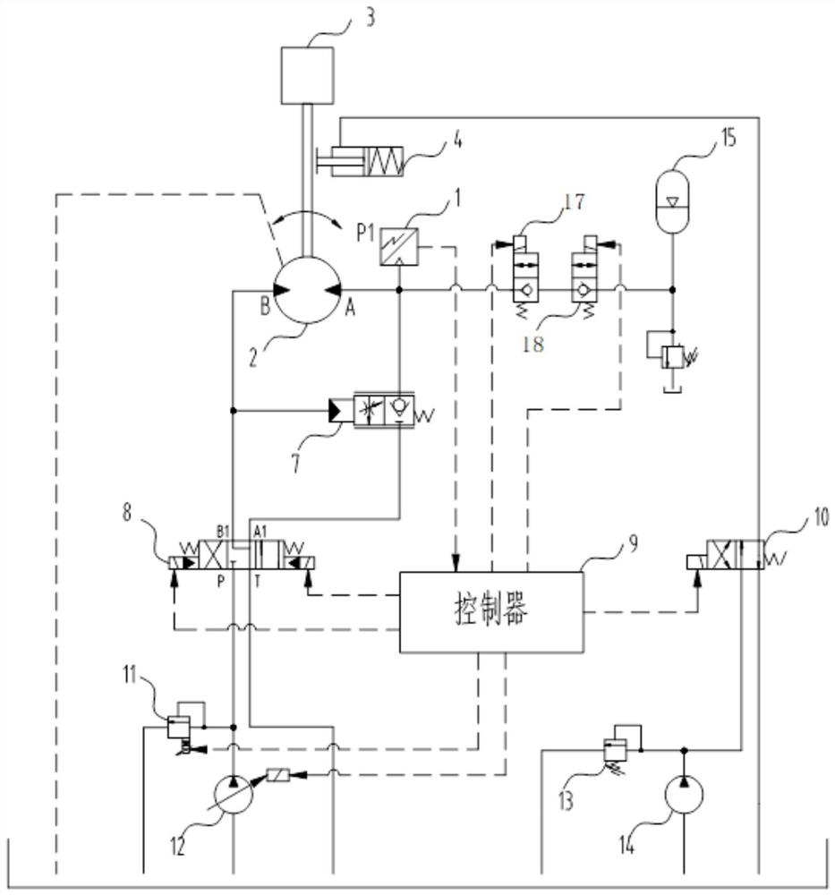
[0105] This embodiment provides a winch hydraulic control system, please refer to image 3 , this winch hydraulic control system includes:

[0106] The winch hydraulic motor 2 is provided with a first oil port for controlling lifting and a second oil port for controlling lowering;

[0107] The brake 4, the brake 4 can selectively abut against the output shaft of the winch hydraulic motor 2, so as to control the brake of the winch hydraulic motor 2;

[0108] The main oil pump 12, the main oil pump 12 is connected with the hoist hydraulic motor 2, so as to supply oil to the hoist hydraulic motor 2;

[0109] The first reversing valve 8, the first reversing valve 8 is arranged between the hoist hydraulic motor 2 and the main oil pump 12, the first reversing valve 8 is used to control the communication between the main oil pump 12 and the first oil port or the second oil port ;

[0110] A balance valve 7, the balance valve 7 is arranged between the first oil port and the second ...


PUM


Abstract

The invention provides a hydraulic control system for a winch and a crane, and belongs to the field of construction mechanisms. The system comprises a hydraulic motor of the winch, a brake, a main oilpump which is connected to the hydraulic motor of the winch and is used for supplying oil to the hydraulic motor of the winch, a first reversing valve which is arranged between the hydraulic motor ofthe winch and the main oil pump, a balancing valve which is arranged between a first oil port and a second oil port, an oil tank which is correspondingly connected to the main oil pump and the firstreversing valve, and an oil pressure control mechanism. With the adoption of the hydraulic control system for the winch and the crane, the problems of hydraulic impacting, hook gliding and opposite rotating of the hydraulic motor, the gliding friction of the brake, the mechanical collision and noise between inner teeth of a speed reducer, and slight settlement of a heavy matter can be effectivelyprevented. Therefore, the service lives of the brake and the speed reducer can be effectively prolonged; the stability, accuracy and safety of winching can be improved; and the operation experience ofa customer is increased.

Description

technical field [0001] The invention relates to the field of engineering machinery, in particular to a winch hydraulic control system and a crane. Background technique [0002] The hoisting system of hydraulically driven engineering cranes can be divided into open hoisting and closed hoisting according to the principle of hydraulic circuit. The open winch system includes wire rope, reel, reducer (with normally closed brake), hydraulic motor, balance valve (usually set on the hook side of the winch), main reversing valve, main relief valve, main oil pump, Brake control valve, pilot relief valve, pilot oil pump, etc. Its working principle is: the main oil pump controls the hydraulic motor through the main reversing valve, drives the reducer + reel and wire rope, and realizes hoisting, hoisting, lifting and dropping of the hook, and the opening and closing of the brake is controlled by the brake control valve through the pilot oil. source control. During this process, the br...

Claims


Application Information

Patent Timeline
Patent Type & Authority Patents(China)
IPC IPC(8): B66D1/44
CPCB66D1/44
Inventor 邹兴龙王圣磊唐海军
Owner SANY AUTOMOBILE HOISTING MACHINERY
Why Eureka
Eureka Blog
Learn More