
Method and system for controlling hydraulic motor

A hydraulic motor and control system technology, applied in servo motors, fluid pressure actuation devices, mechanical equipment, etc., can solve problems affecting service life and hydraulic shock, and achieve the effect of avoiding hydraulic shock and improving service life.

Active Publication Date: 2013-02-27
ZOOMLION HEAVY IND CO LTD
View PDF4 Cites 0 Cited by
  • Summary
  • Abstract
  • Description
  • Claims
  • Application Information

AI Technical Summary

Problems solved by technology

[0005] The main purpose of the present invention is to provide a hydraulic motor control method and system to solve the problem that in the prior art, during the high-low speed switching process of the hydraulic motor, the instantaneous change from a large swing angle to a small swing angle will cause hydraulic shock, resulting in serious Problems affecting its service life

Method used


Image

  • Method and system for controlling hydraulic motor
  • Method and system for controlling hydraulic motor
  • Method and system for controlling hydraulic motor

Examples


Embodiment Construction

[0027] It should be noted that, in the case of no conflict, the embodiments in the present application and the features in the embodiments can be combined with each other. The present invention will be described in detail below with reference to the accompanying drawings and examples.

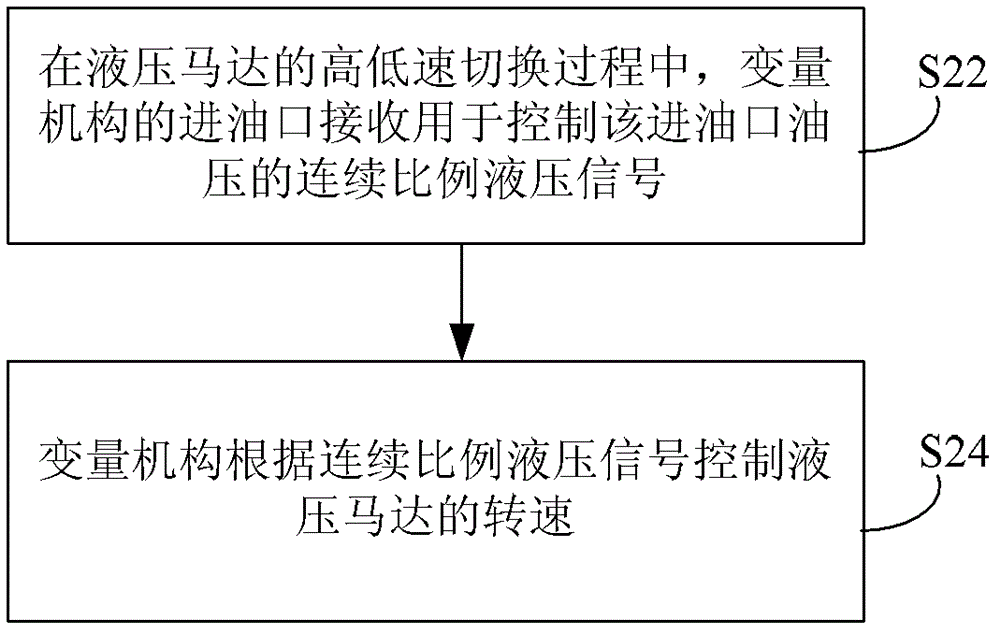
[0028] figure 2 is a flow chart of main steps of a method for controlling a hydraulic motor according to an embodiment of the present invention, wherein the hydraulic motor controlled by the method is connected to a variable mechanism for controlling the rotational speed of the hydraulic motor, such as figure 2 As shown, the method mainly includes the following steps:

[0029] Step S22: During the high-low speed switching process of the hydraulic motor, the oil inlet of the variable mechanism receives a continuous proportional hydraulic signal for controlling the oil pressure of the oil inlet;

[0030] In this step, there can be various devices for providing continuous proportional hydrauli...


PUM


Abstract

The invention provides a method and a system for controlling a hydraulic motor, which aims to solve the problems that the service life of the hydraulic motor is seriously influenced by hydraulic impacts generated when a large oscillation angle is transiently changed into a small oscillation angle in the high / low speed switching process of the hydraulic motor in the prior art. The method comprisesthe following steps that: in the high / low speed switching process of the hydraulic motor, an oil inlet of a variable mechanism receives a continuous proportion hydraulic signal which is used for controlling oil pressure at the oil inlet; and the variable mechanism controls the rotating speed of the hydraulic motor according to the continuous proportion hydraulic signal. Due to the adoption of thetechnical scheme, the condition that the hydraulic motor is positioned in the stepless speed change state in the high / low speed switching process is facilitated, the hydraulic impacts are effectivelyprevented, and the service life of the hydraulic motor is prolonged.

Description

technical field [0001] The invention relates to the field of engineering machinery, in particular to a control method and system for a hydraulic motor. Background technique [0002] figure 1 It is a structural schematic diagram of the control system of the hydraulic motor of the crane winch system in the prior art, such as figure 1 As shown, the hydraulic motor 11 of the hoisting system is connected with a variable mechanism 12 for controlling its rotational speed, and the hydraulic motor 11 is also connected with a reversing valve 16 for controlling its rotation direction. The oil inlet X of the variable mechanism 12 is connected to the solenoid valve 13 through the oil circuit, and the solenoid valve 13 is also connected to the control oil source 14. The solenoid valve 13 controls the pressure at the oil inlet X of the variable mechanism 12, and then controls the pressure of the hydraulic motor 11. Angle. The initial swing angle of the hydraulic motor 11 is a large swin...

Claims


Application Information

Patent Timeline
Patent Type & Authority Patents(China)
IPC IPC(8): F15B11/02
Inventor 何伟宋建清刘建华
Owner ZOOMLION HEAVY IND CO LTD
Learn More