A method and device for tracking a moving object
A technology for moving objects and target objects, which is applied in the field of artificial intelligence and can solve problems such as loss of tracking of moving objects
- Summary
- Abstract
- Description
- Claims
- Application Information
AI Technical Summary
Problems solved by technology
Method used
Image
Examples
Embodiment 1
[0048] Figure 5 A schematic diagram of the moving object tracking process provided by the embodiment of the present invention, the process includes the following steps:
[0049] S101: For each frame image in the continuous frame images, divide the frame image into at least two sub-images according to a preset rule, and determine a dividing line between every two adjacent sub-images.
[0050] Embodiments of the present invention provide a moving object tracking method applied to an electronic device, and the electronic device may be a PC, a tablet computer, or an image acquisition device.
[0051] The electronic device can obtain continuous frame images. If the electronic device is an image acquisition device, the electronic device itself can directly obtain continuous frame images. If the electronic device is a PC, tablet computer, etc., it can receive the continuous frame images sent by the image acquisition device. .
[0052] For each frame image in the continuous frame i...
Embodiment 2
[0067] In order to improve the efficiency of determining the moving object in the image, on the basis of the above embodiments, in the embodiment of the present invention, for each target object in each sub-image of each frame of image, according to the target object Coordinate information, judging whether the target object includes at the dividing line of the sub-image:
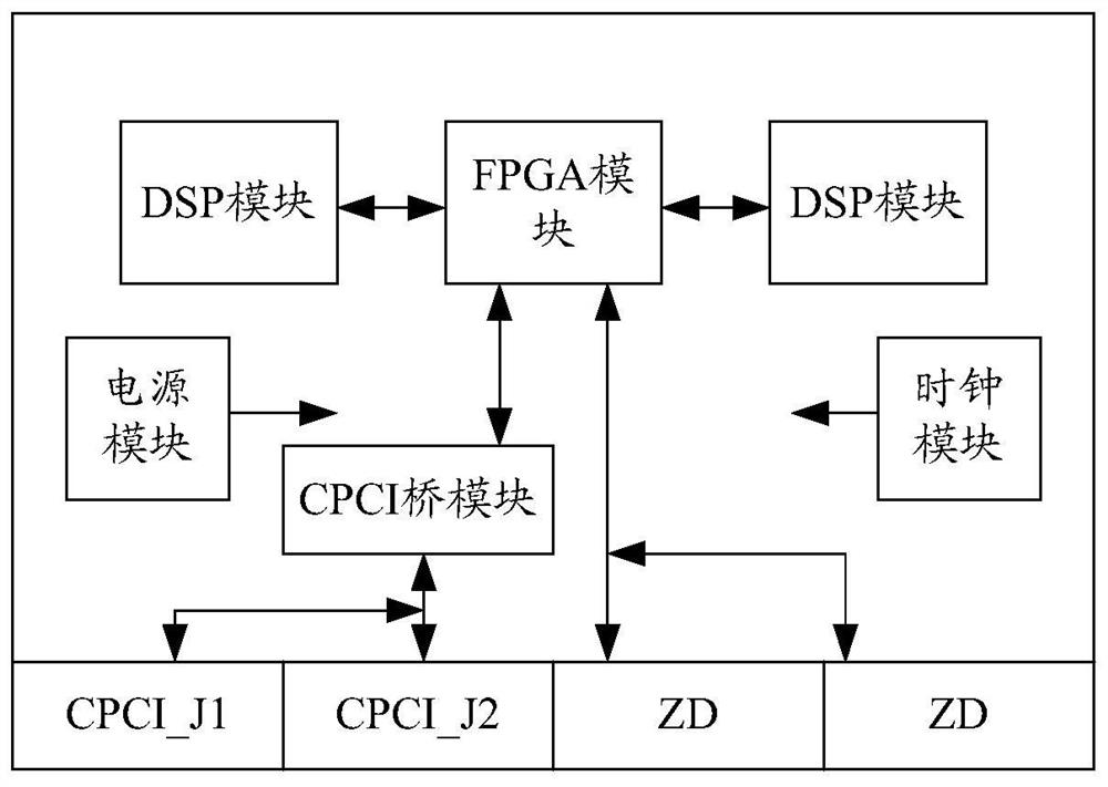
[0068] For each frame image, each sub-image of the frame image is sent to the corresponding digital signal processor DSP; for each target object in each sub-image, the corresponding digital signal processor DSP according to the target object The coordinate information of the target object is judged whether the target object is at the dividing line of the sub-image.
[0069] The electronic device includes a plurality of DSPs, after each frame of image is divided into at least two sub-images according to preset rules, for each frame of image, each sub-image of the frame of image is sent to the corresponding DS...
Embodiment 3
[0073] On the basis of the above embodiments, in the embodiment of the present invention, if the target object is not at the dividing line of the sub-image, the method further includes:
[0074] Based on the sub-image and the sub-image corresponding to the previous frame image of the frame image, a moving object detection algorithm is used to determine whether the target object is a moving object;
[0075] If yes, determine the target object as a moving object; and track the moving object.
[0076] For each target object in each sub-image of each frame image, if it is judged that the target object is not at the dividing line of the sub-image, based on the sub-image and the sub-image corresponding to the previous frame image of the frame image, a motion The object detection algorithm judges whether the target object is a moving object, and if so, determines the target object as a moving object. Wherein, the moving object detection algorithm may be an improved Chan-Vese algorit...
PUM
 Abstract
Description
Claims
Application Information
 - R&D
- Intellectual Property
- Life Sciences
- Materials
- Tech Scout
- Unparalleled Data Quality
- Higher Quality Content
- 60% Fewer Hallucinations
Browse by: Latest US Patents, China's latest patents, Technical Efficacy Thesaurus, Application Domain, Technology Topic, Popular Technical Reports.
© 2025 PatSnap. All rights reserved.Legal|Privacy policy|Modern Slavery Act Transparency Statement|Sitemap|About US| Contact US: help@patsnap.com


