

A wireless charging method and system
A wireless charging and circuit technology, applied in the field of communication, can solve the problem that the energy transmitter cannot adjust the energy output, so as to improve the charging efficiency and avoid mutual interference
- Summary
- Abstract
- Description
- Claims
- Application Information
AI Technical Summary
Problems solved by technology
Method used
Image

Examples
Embodiment 1
[0044] According to an embodiment of the present invention, an embodiment of a wireless charging method is also provided. It should be noted that the steps shown in the flowcharts of the accompanying drawings can be executed in a computer system such as a set of computer-executable instructions, and, although A logical order is shown in the flowcharts, but in some cases the steps shown or described may be performed in an order different from that shown or described herein.
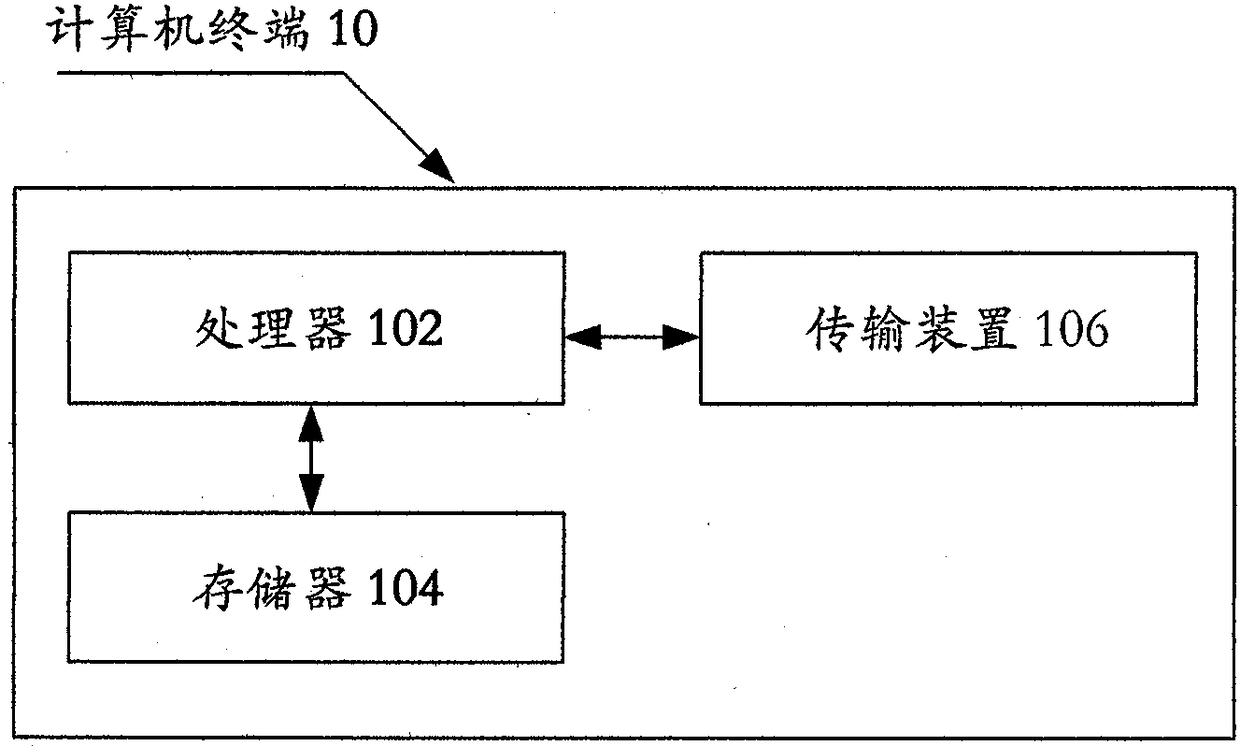
[0045] The method embodiment provided in Embodiment 1 of the present application may be executed in a mobile terminal, a computer terminal, or a similar computing device. Take running on a computer terminal as an example, figure 1 It is a hardware structure block diagram of a computer terminal of a wireless charging method according to an embodiment of the present invention. Such as figure 1 As shown, the computer terminal 10 may include one or more (only one is shown in the figure) processors 102 (the p...
Embodiment 2
[0064] Figure 4 is a structural block diagram of a wireless charging system according to Embodiment 2 of the present invention. Such as Figure 4 As shown, in the embodiment of the present invention, a wireless charging system is also provided, including:
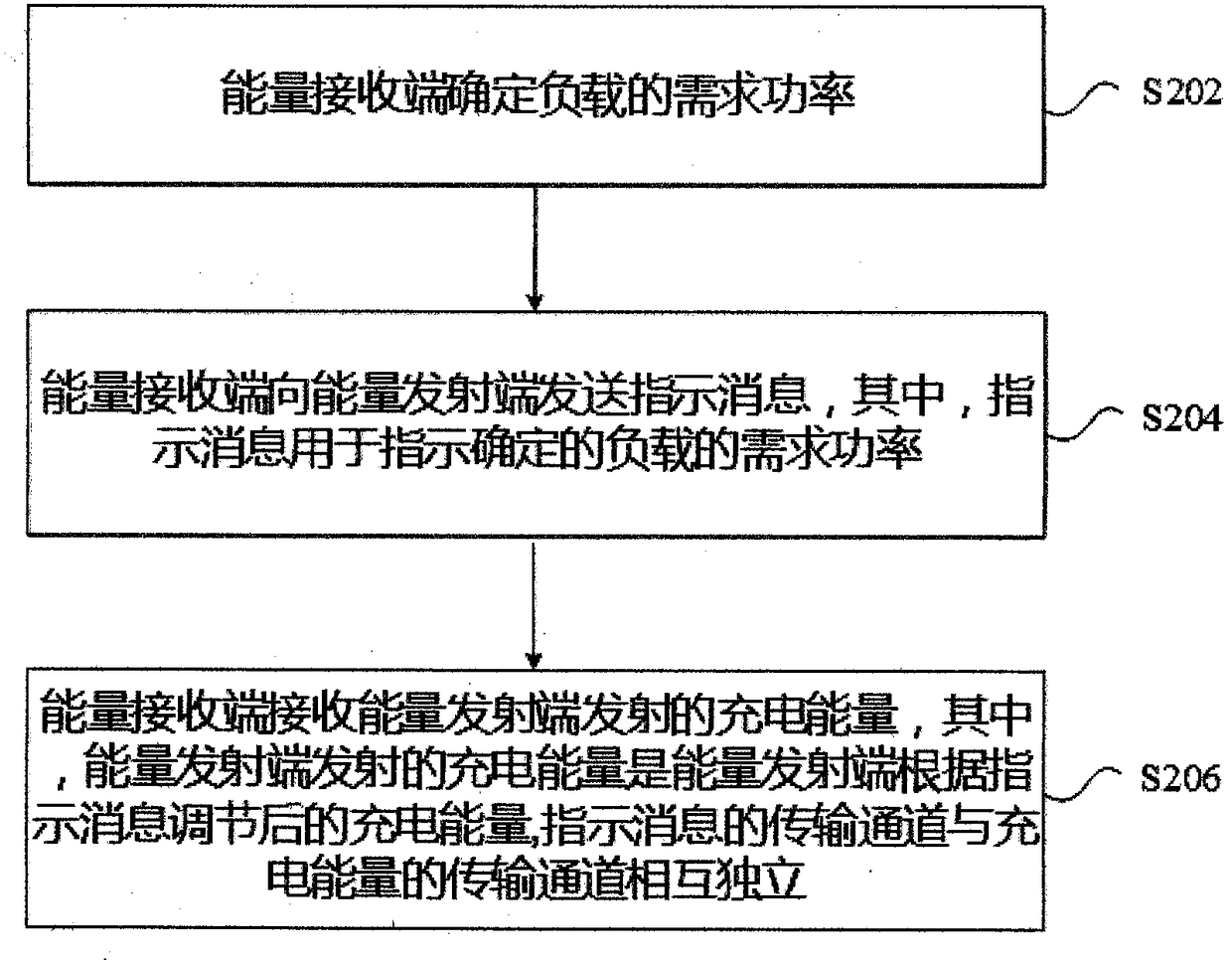
[0065] The energy receiving end 40 is connected to the load 42 for determining the required power of the load 42, and sending an indication message to the energy transmitting end, wherein the indication message is used to indicate the determined required power of the load;
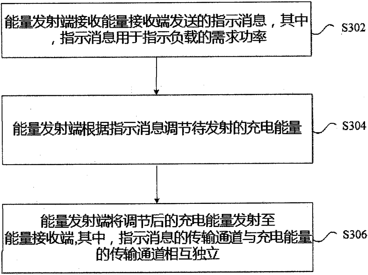
[0066] The energy transmitting end 44 is used to adjust the charging energy according to the indication message, and transmit the adjusted charging energy to the energy receiving end 40, wherein the transmission channel of the indication message and the transmission channel of the charging energy are independent of each other.
[0067] Through the above system, the energy receiving end determines the required power of the load, and sends an indicatio...
PUM
 Abstract
Description
Claims
Application Information