
A cardiac disease arrhythmia detection device

A technology for irregular heart rate and inspection devices, which is applied in the measurement of pulse rate/heart rate, medical science, surgical equipment, etc. It can solve the problems of inconvenience, inability to adjust the heart rate sensor, and inconvenient heart rate detection for patients, so as to achieve smooth left and right movement, up and down The effect of mobile stabilization

Inactive Publication Date: 2019-01-08
THE AFFILIATED HOSPITAL OF QINGDAO UNIV
View PDF8 Cites 2 Cited by
  • Summary
  • Abstract
  • Description
  • Claims
  • Application Information

AI Technical Summary

Benefits of technology

The invention relates to an electrocardiography (ECG) checker used during medical procedures such as angioplasty or ablation therapy where there are often variations between individuals who have their hearts beating too much at one time compared to another person without any problems. This problem arises because some peoples may want certain things they donate while others cannot afford them. To solve these issues, special devices called ECG machines were developed which measure electrical activity on specific parts of the body. These machines work well but require trained staff members to operate properly.

Problems solved by technology

This patented technical problem addressed by this patents relates to improving an electrocardiogram (ECG) measurement system that can adapt its location based on how patients are tall with their ECG sensors located at varying locations around them.

Method used


Image

  • A cardiac disease arrhythmia detection device
  • A cardiac disease arrhythmia detection device
  • A cardiac disease arrhythmia detection device

Examples


Embodiment Construction

[0025] The following will clearly and completely describe the technical solutions in the embodiments of the present invention with reference to the accompanying drawings in the embodiments of the present invention. Obviously, the described embodiments are only some, not all, embodiments of the present invention. Based on the embodiments of the present invention, all other embodiments obtained by persons of ordinary skill in the art without making creative efforts belong to the protection scope of the present invention.

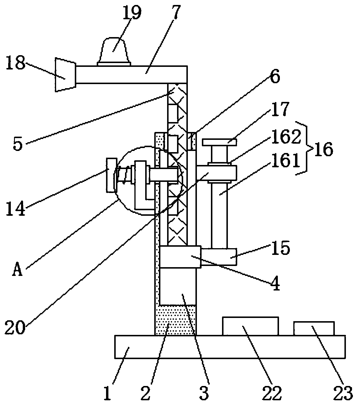
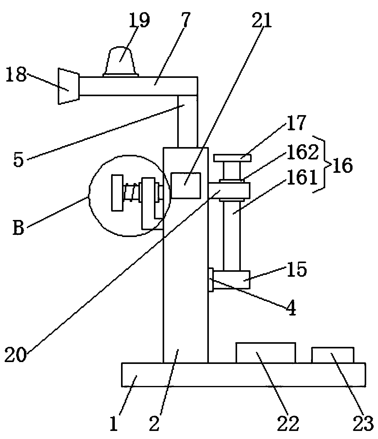
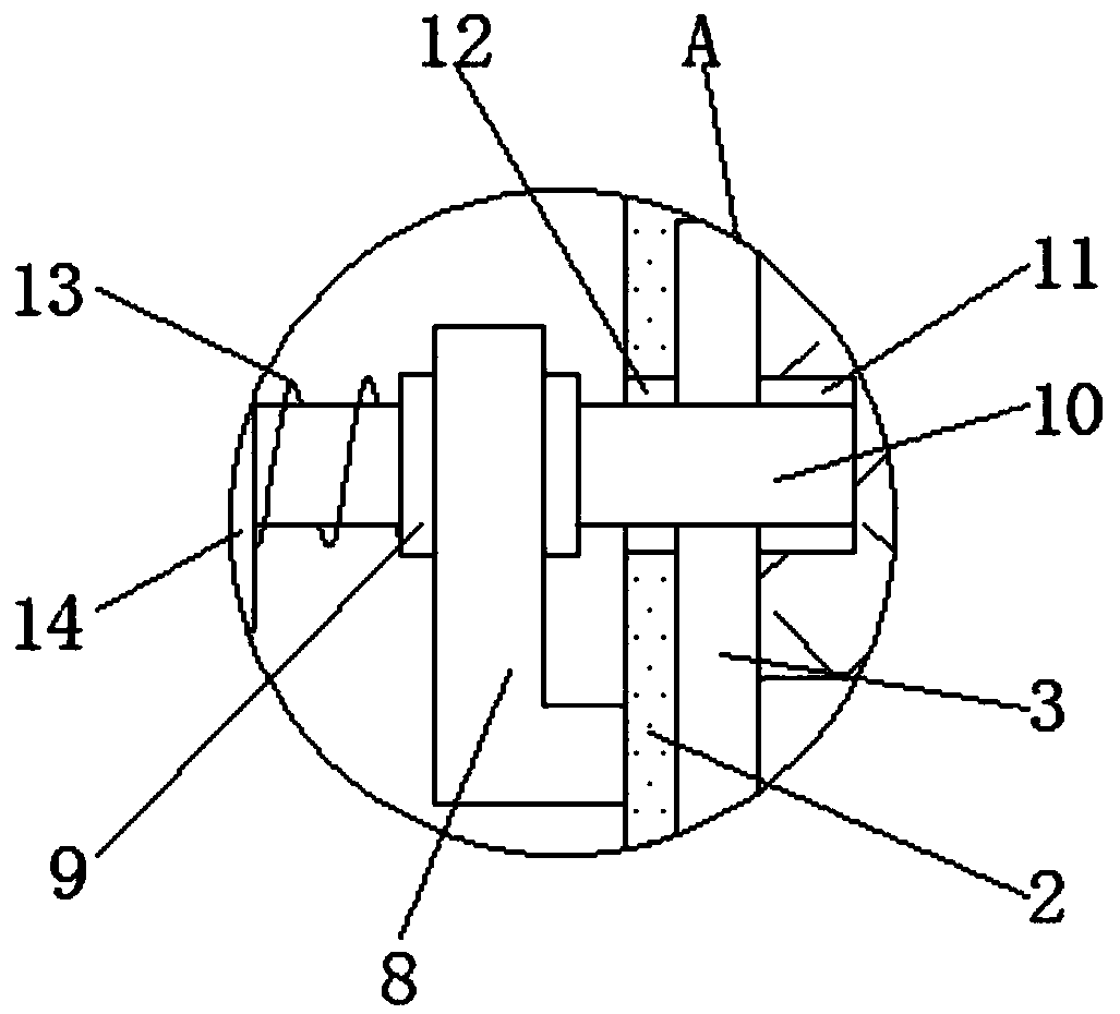
[0026] Such as Figure 1-4 As shown, the present invention provides a technical solution: a cardiac arrhythmia inspection device, including a base plate 1, the right side of the upper surface of the base plate 1 is fixedly connected with a power source 22 and a switch 23, and the switch 23 is located on the right side of the power source 22 The output end of the power supply 22 is electrically connected to the input end of the switch 23 through a wire, the out...


PUM


Abstract

The invention discloses a cardiac disease arrhythmia detection device which relates to the technical field of medical equipment. The device comprises a bottom plate, a support plate is fixedly connected to the left side of the upper surface of the bottom plate, a sliding groove is arranged on the right side of the support plate, a sliding block is slidably connected in the sliding groove, and a movable rod is fixedly connected to the upper surface of the sliding block. According to the cardiac disease arrhythmia detection device, through arranging a first baffle and a second baffle, the firstbaffle is pulled to the left, the first baffle drives the first sliding rod to move to the left, As that first slide rod disengages from the snap slot, the second slide bar is pulled upward by the second baffle, When the heart rate sensor corresponds to the heart position of the patient, the position of the heart rate sensor can be adjusted by releasing the first baffle, thereby facilitating people to detect the heart rate of the patient with different height, thereby bringing convenience to people when using the heart rate irregularity detection device. The invention relates to a heart rate sensor, which comprises a sliding rod, a heart rate sensor and a heart rate sensor.

Description


Claims


Application Information

Patent Timeline
Owner THE AFFILIATED HOSPITAL OF QINGDAO UNIV
Learn More