A leg fracture retractor

A traction device and leg technology, which is applied in the field of leg fracture traction devices, can solve the problems of secondary injury of patients, difficulty in controlling their own hand strength, etc., and achieve the effect of preventing secondary injury.

Active Publication Date: 2019-01-08
杜秀艳
View PDF28 Cites 1 Cited by
  • Summary
  • Abstract
  • Description
  • Claims
  • Application Information

AI Technical Summary

Problems solved by technology

[0003] In order to overcome the disadvantage that it is difficult for the medical staff to control the strength of their own hands by pulling the patient's legs with their hands, which will cause secondary injury to the patient, the purpose of the present invention is to provide a Leg Fracture Retractors to Prevent Secondary Injury

Method used


Image

  • A leg fracture retractor
  • A leg fracture retractor
  • A leg fracture retractor

Examples


Embodiment 1

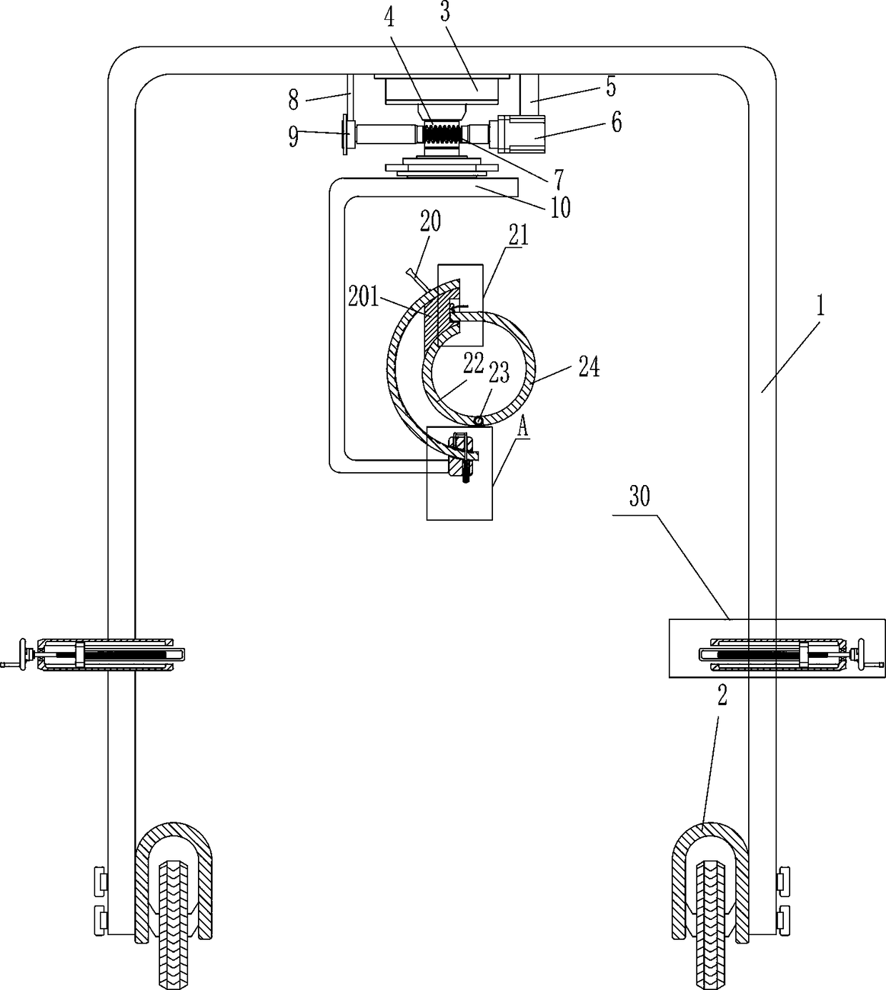
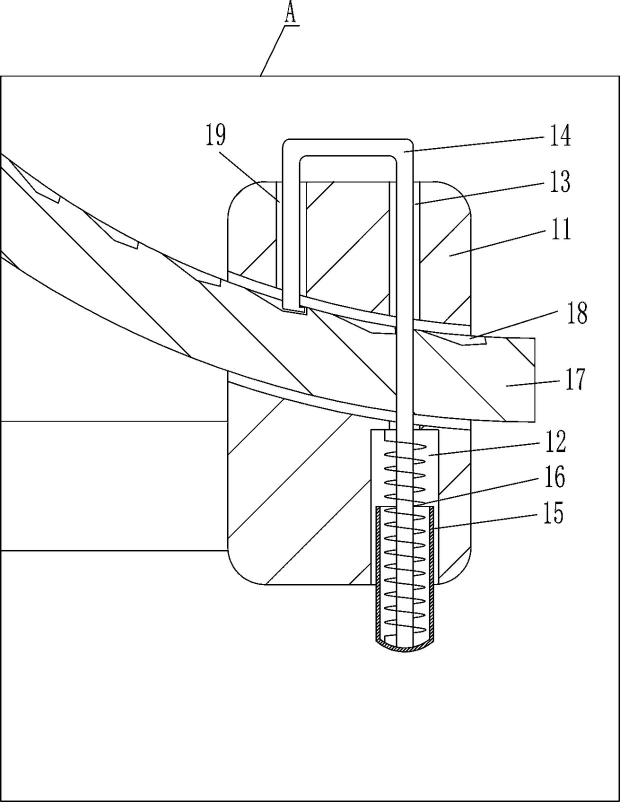
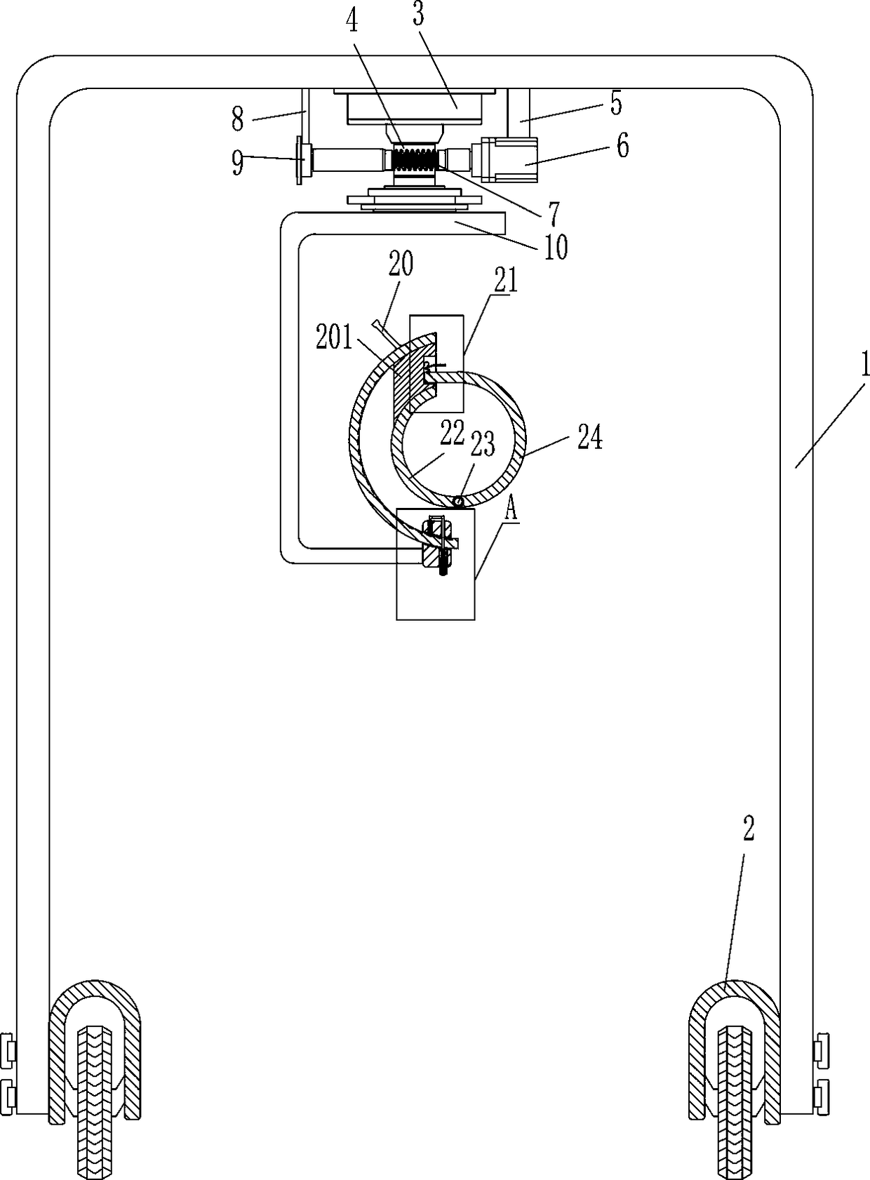
[0019] A leg fracture retractor such as Figure 1-5 As shown, it includes an n-shaped frame 1, a wheel 2, a bearing seat 3, a first gear 4, a first pole 5, a motor 6, an elongated gear 7, a second pole 8, a first bearing 9, and a C-shaped frame 10. Arc-shaped guide block 11, guide rod 14, hollow pressure block 15, first spring 16, arc-shaped slide bar 17, handle 20 and clamping mechanism 21 for clamping legs, left and right sides of the bottom of n-shaped frame 1 All are equipped with wheels 2 for moving, the first gear 4 is installed on the bearing seat 3 through the rotating shaft, the bearing seat 3 is installed in the middle of the top in the n-shaped frame 1, and the first strut 5 is installed on the top in the n-shaped frame 1 On the right side, the bottom end of the first pole 5 is equipped with a motor 6, and the first bearing 9 is installed on the left side of the top in the n-shaped frame 1 by the second pole 8, and a long shaft is fixedly installed in the first bear...

Embodiment 2

[0021] A leg fracture retractor such as Figure 1-5As shown, it includes an n-shaped frame 1, a wheel 2, a bearing seat 3, a first gear 4, a first pole 5, a motor 6, an elongated gear 7, a second pole 8, a first bearing 9, and a C-shaped frame 10. Arc-shaped guide block 11, guide rod 14, hollow pressure block 15, first spring 16, arc-shaped slide bar 17, handle 20 and clamping mechanism 21 for clamping legs, left and right sides of the bottom of n-shaped frame 1 All are equipped with wheels 2 for moving, the first gear 4 is installed on the bearing seat 3 through the rotating shaft, the bearing seat 3 is installed in the middle of the top in the n-shaped frame 1, and the first strut 5 is installed on the top in the n-shaped frame 1 On the right side, the bottom end of the first pole 5 is equipped with a motor 6, and the first bearing 9 is installed on the left side of the top in the n-shaped frame 1 by the second pole 8, and a long shaft is fixedly installed in the first beari...

Embodiment 3

[0024] A leg fracture retractor such as Figure 1-5 As shown, it includes an n-shaped frame 1, a wheel 2, a bearing seat 3, a first gear 4, a first pole 5, a motor 6, an elongated gear 7, a second pole 8, a first bearing 9, and a C-shaped frame 10. Arc-shaped guide block 11, guide rod 14, hollow pressure block 15, first spring 16, arc-shaped slide bar 17, handle 20 and clamping mechanism 21 for clamping legs, left and right sides of the bottom of n-shaped frame 1 All are equipped with wheels 2 for moving, the first gear 4 is installed on the bearing seat 3 through the rotating shaft, the bearing seat 3 is installed in the middle of the top in the n-shaped frame 1, and the first strut 5 is installed on the top in the n-shaped frame 1 On the right side, the bottom end of the first pole 5 is equipped with a motor 6, and the first bearing 9 is installed on the left side of the top in the n-shaped frame 1 by the second pole 8, and a long shaft is fixedly installed in the first bear...


PUM


Abstract

The invention relates to a retractor, in particular to a leg fracture retractor. It is an object of the present invention to provide a leg fracture retractor capable of controlling hand strength and preventing secondary injury. The technical scheme is as follows: the leg fracture tractor comprises an n-shaped frame, a wheel, a bearing seat, a first gear, a first strut, a motor, a long gear, a second strut, a first bearing, a C-shaped frame, an arc guide block, etc.. The left and right sides of the bottom of the n-shaped frame are provided with wheels for moving, the first gear is mounted on the bearing housing through a rotating shaft, the bearing housing is mounted in the middle of the top of the n-shaped frame, and the first strut is mounted on the right side of the top of the n-shaped frame. As that long gear is rotate by the starting motor of the medical staff, the angle of the clam mechanism can be adjusted, and the legs of the patient can be fixed by the clam mechanism, so that the medical staff can conveniently pull the legs of the patient.

Description

technical field [0001] The invention relates to a distractor, in particular to a distractor for leg fractures. Background technique [0002] After an orthopedic patient has a leg fracture, the medical staff needs to use their hands to pull the patient's leg, so that the fractured patient's leg can return to normal. It is difficult for the medical staff to control the strength of their own hands when tractioning the patient, which will cause secondary injury to the patient. In order to prevent secondary injury to the patient, the medical staff will use force sensing The device controls the strength of the hands, but if the strength is too small, it is difficult to achieve the purpose of pulling the patient's legs. Contents of the invention [0003] In order to overcome the disadvantage that it is difficult for the medical staff to control the strength of their own hands by pulling the patient's legs with their hands, which will cause secondary injury to the patient, the pu...

Claims


Application Information

Patent Timeline
Patent Type & Authority Applications(China)
IPC IPC(8): A61F5/048A61F5/058A61G7/05
CPCA61F5/048A61F5/0585A61G7/05A61G2210/10
Inventor 周睿
Owner 杜秀艳
Why Eureka
Try Eureka