Bottom pouring type purification smelting device and method

A smelting device, bottom-injection technology, applied in the field of bottom-injection purification and purification smelting device, can solve the problems of pollution, high content of harmful gas, low quality of alloy melt, etc., reduce cost, reduce inclusion defects, and facilitate operation Effect

Pending Publication Date: 2019-01-08
INST OF METAL RESEARCH - CHINESE ACAD OF SCI
View PDF10 Cites 1 Cited by
  • Summary
  • Abstract
  • Description
  • Claims
  • Application Information

AI Technical Summary

Problems solved by technology

When the bottom injection technology is used alone, the oxides on the surface of the alloy liquid can be prevented from entering the casting or alloy ingot through the bottom injection, but the alloy liquid has a lot of harmful gases because it has not been purified, and the bottom injection is generally drawn from the top The way of stopper rod, the stopper rod is immersed in the alloy melt, which can pollute the alloy liquid to a certain extent, resulting in low quality alloy melt

Method used


Image

  • Bottom pouring type purification smelting device and method
  • Bottom pouring type purification smelting device and method
  • Bottom pouring type purification smelting device and method

Examples


Embodiment 1

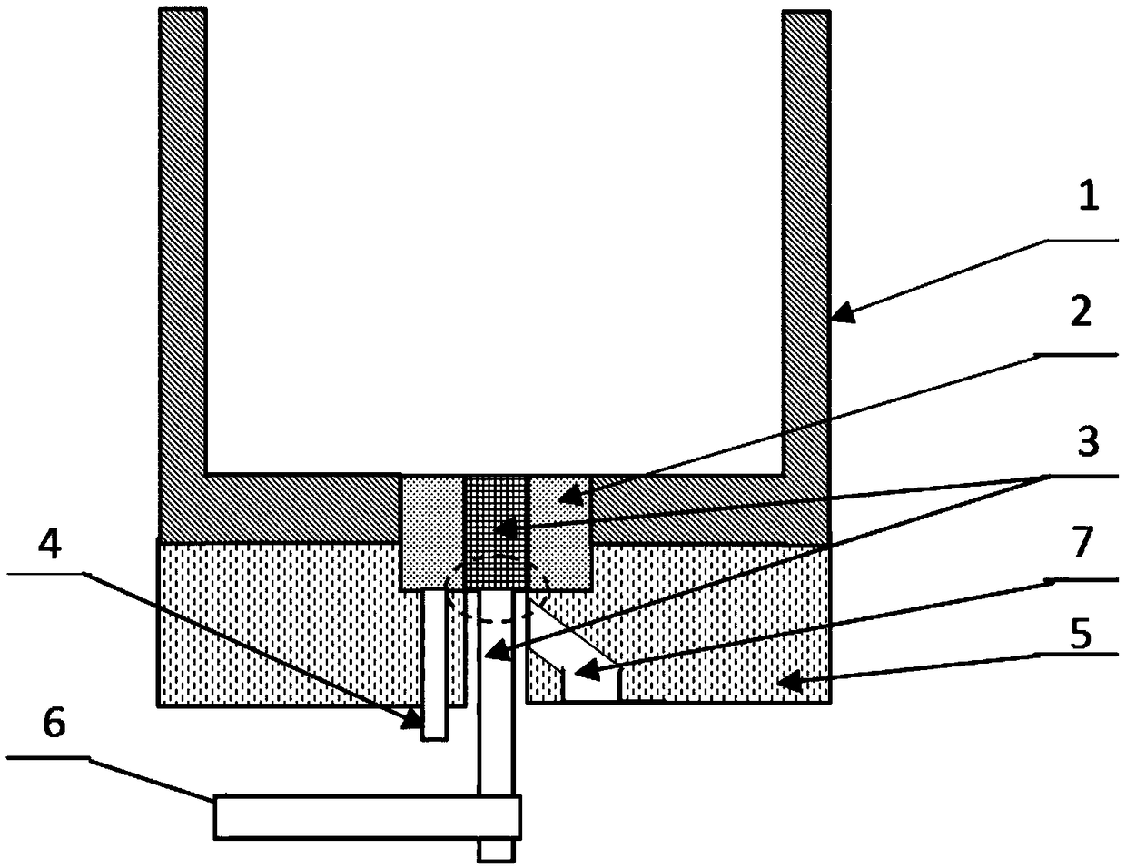
[0045] Use the smelting device to carry out the bottom pouring purification and purification smelting method, wherein, the bottom pouring device in this embodiment is figure 1 The shown rod-shaped drawing device, the method comprises the steps of:

[0046] (1) Before alloy smelting, connect the bottom blowing argon device to the bottom of the ladle or crucible, and insert the ceramic stopper rod of the rod-shaped drawing device in the middle of the bottom blowing argon device;

[0047] (2) The melted alloy melt is first subjected to high-temperature refining in the ladle or crucible 1 at a temperature of 100-150°C above the melting point of the alloy, and the refining time is generally 10-30min to initially remove impurities and harmful gases in the melt;

[0048] (3) After the alloy is refined, open the inlet valve on the argon gas inlet pipe, pass the argon gas from the argon gas inlet pipe into the bottom blowing argon device and send it into the alloy melt, and the argon g...

Embodiment 2

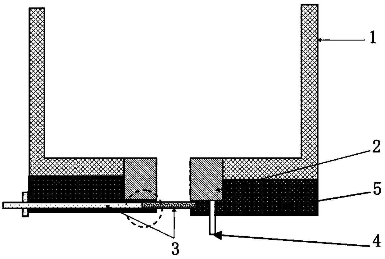
[0052] Use the smelting device to carry out the bottom pouring purification and purification smelting method, wherein, the bottom pouring device in this embodiment is figure 2 As shown in the drawing device, the method comprises the steps of:

[0053] (1) Before smelting steel, superalloy or other alloys, connect the bottom blowing argon device at the bottom of the ladle or crucible, and move the isolation plate of the drawing device to the bottom of the bottom blowing argon device;

[0054] (2) After the alloy is melted, heat it up to 100-150°C above the melting point of the alloy for high-temperature refining of the melt, and the refining time is 10-30 minutes.

[0055] (3) Open the argon gas inlet valve, send the argon gas into the melt from the bottom through the breathable brick, make it gradually rise from the bottom to the liquid level, adjust the argon gas pressure to 0.1MPa-0.6MPa, and the purification time is 10- 20min.

[0056] (4) When the melt temperature meets...


PUM


Abstract

The invention discloses a bottom pouring type purification smelting device and method, and belongs to the technical field of casting. The smelting device comprises an annular bottom argon blowing device and a bottom pouring device; the bottom argon blowing device is arranged at the bottom of a pouring ladle or a crucible, the upper end of the bottom argon blowing device is detachably connected with the bottom of the pouring ladle or the crucible, the bottom end of the bottom argon blowing device is connected with an argon feeding pipe, argon enters alloy liquid in the pouring ladle or the crucible from the argon feeding pipe through the bottom argon blowing device, and the alloy liquid is purified; and the bottom pouring device is a rod-like pulling device which is inlaid in a middle through hole of the bottom argon blowing device or a plate-like pulling device which is arranged below the bottom argon blowing device. When the smelting device is used, the argon is fed into melt to purify the melt through the bottom argon blowing device, then, the bottom pouring device is moved downwards or removed for bottom pouring type pouring. Through the bottom pouring type purification smeltingdevice and method, the bottom argon blowing and bottom pouring functions can be achieved at the same time, the alloy liquid can be purified better, and accordingly, the quality of the alloy liquid isimproved.

Description

technical field [0001] The invention relates to the field of casting technology, in particular to a bottom-injection purification and purification smelting device and a smelting method. Background technique [0002] During the casting process, there will be a small amount of harmful gas attached to the alloy liquid. During conventional casting, the harmful gas will enter the pouring mold together with the alloy liquid, and then remain in the casting or alloy ingot, resulting in damage to the casting or alloy ingot. At the same time, some scum or other oxide inclusions will be produced on the surface of the alloy liquid during the smelting process, which will also enter the casting or alloy ingot during ordinary casting, causing defects such as inclusions, thereby reducing the product qualification rate. However, the existing devices and processes can only realize bottom blowing argon purification or bottom injection pouring alone. [0003] When the bottom blowing argon proc...

Claims


Application Information

Patent Timeline
Patent Type & Authority Applications(China)
IPC IPC(8): B22D1/00C21C7/00C21C7/072C22B9/05
CPCC21C7/0075C21C7/072C22B9/05B22D1/005
Inventor 谢君侯桂臣仉凤江荀淑玲谭明晖王振江周亦胄孙晓峰
Owner INST OF METAL RESEARCH - CHINESE ACAD OF SCI
Why Eureka
Try Eureka