
Device capable of adjusting size during metal wire drawing

A metal wire drawing and adjustable technology, which is applied in the direction of grinding drive device, metal processing equipment, grinding workpiece support, etc., can solve the problems of reducing production efficiency, wasting manufacturing time, and unfavorable production, so as to improve productivity and prevent The effect of uneven drawing and convenient operation

Pending Publication Date: 2019-01-08
湖州市练市创鑫金属拉丝厂
View PDF0 Cites 4 Cited by
  • Summary
  • Abstract
  • Description
  • Claims
  • Application Information

AI Technical Summary

Problems solved by technology

[0004] Aiming at the deficiencies of the prior art, the present invention provides a metal drawing adjustable size device, which has the advantages of placing metal plates of different sizes, etc., and solves the problem that during the manufacturing process of metal drawing, due to the different sizes of the metal plates, different sizes may need to be replaced. When operating on a dedicated console, when walking back and forth, the manufacturing time is wasted, the production efficiency is virtually reduced, it is not conducive to production, and it brings inconvenience to people.

Method used


Image

  • Device capable of adjusting size during metal wire drawing
  • Device capable of adjusting size during metal wire drawing

Examples


Embodiment Construction

[0020] The following will clearly and completely describe the technical solutions in the embodiments of the present invention with reference to the accompanying drawings in the embodiments of the present invention. Obviously, the described embodiments are only some, not all, embodiments of the present invention. Based on the embodiments of the present invention, all other embodiments obtained by persons of ordinary skill in the art without making creative efforts belong to the protection scope of the present invention.

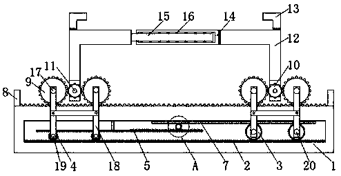
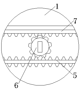
[0021] see Figure 1-2 , a metal wire drawing adjustable size device, comprising a bottom plate 1, a single-sided rack 2 is fixedly installed on the lower end of the inner cavity of the bottom plate 1, and the two ends of the teeth of the single-sided rack 2 are meshed with rotating gears-3 respectively and the rotating gear 2 4, the teeth of the rotating gear 2 4 are meshed with a double-sided rack 5, the upper surface of the double-sided rack 5 is slidably c...


PUM


Abstract

The invention relates to the technical field of metal wire drawing and discloses a device capable of adjusting the size during metal wire drawing. The device comprises a bottom plate. A single-face tooth bar is fixedly installed at the lower end of an inner cavity of the bottom plate, and first rotating gears and second rotating gears are engaged with the two ends of the tooth positions of the single-face tooth bar. A double-face tooth bar is engaged with the tooth positions of the second rotating gears, and a rotating gear is engaged with the tooth position of the right end of the double-facetooth bar. A sliding tooth bar is engaged with the tooth position of the upper end of the rotating gear, and the right end of the sliding tooth bar is engaged with the first rotating gears. Stop blocks are fixedly installed at the two ends of the upper surface of the bottom plate. By means of the device, a metal plate can be effectively clamped through clamping pillars, the metal plate is prevented from jittering in the wire drawing process, the phenomenon that the putting position of the metal plate is deviated, and attractiveness of metal in the wire drawing process is affected is avoided,the function of fixing the metal plate is achieved, the metal plate can be fixed, and the phenomenon that wire drawing on the metal plate is not uniform due to deviation of the metal plate, and the overall effect of the finished product is affected is prevented.

Description

technical field [0001] The invention relates to the technical field of metal wire drawing, in particular to a metal wire drawing adjustable size device. Background technique [0002] Metal wire drawing is a manufacturing process in which the aluminum plate is repeatedly scraped out with sandpaper. The main process of the process is deesterification, sand mill, water washing, etc. In the wire drawing process, the special film technology after anodic treatment can make the metal surface generate A film layer containing this metal component can clearly show every tiny silk trace, so that the fine hairline shines in the metal matte. However, during the manufacturing process of metal wire drawing, due to the different sizes of the metal plates, it may require Changing different consoles to operate, when walking back and forth, wastes manufacturing time, virtually reduces production efficiency, is not conducive to production, and brings inconvenience to people. Contents of the i...

Claims


Application Information

Patent Timeline
Patent Type & Authority Applications(China)
IPC IPC(8): B24B41/06B24B47/02
CPCB24B41/068B24B47/02
Inventor 陈炳泉
Owner 湖州市练市创鑫金属拉丝厂
Learn More