Blowing needle base mechanism for blow molding die

A blowing needle seat and blowing mold technology, which is applied in the field of blowing needles for blow molding, can solve the problems of large overall volume, high preparation cost, and increase the volume and weight of the blowing needle seat, so as to ensure the stability of use and reduce production. Cost, effect of reducing machining accuracy and assembly difficulty

Active Publication Date: 2019-01-08
考泰斯(平湖)塑料技术有限公司
View PDF5 Cites 0 Cited by
  • Summary
  • Abstract
  • Description
  • Claims
  • Application Information

AI Technical Summary

Problems solved by technology

However, in the blowing needle seat mechanism of the prior art, the moving cylinder is used to push the assembly of the blowing needle and the telescopic cylinder, so the moving cylinder needs a larger thrust, which makes the volume of the moving cylinder larger, and this increases the volume of the blowing needle seat and weight, so that the lifting cylinder also needs a larger volume of cylinder to realize the lifting of the blowing needle seat, so there is a problem of large overall volume and high production cost

Method used


Image

  • Blowing needle base mechanism for blow molding die
  • Blowing needle base mechanism for blow molding die
  • Blowing needle base mechanism for blow molding die

Examples


Embodiment 1

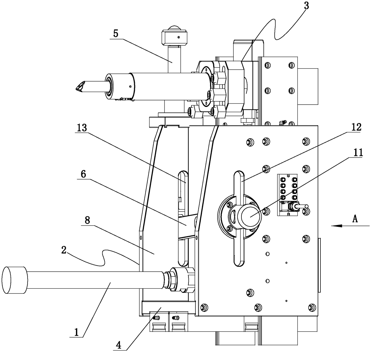
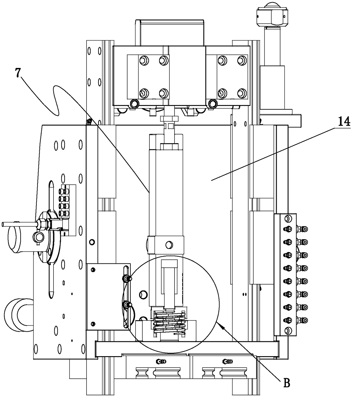
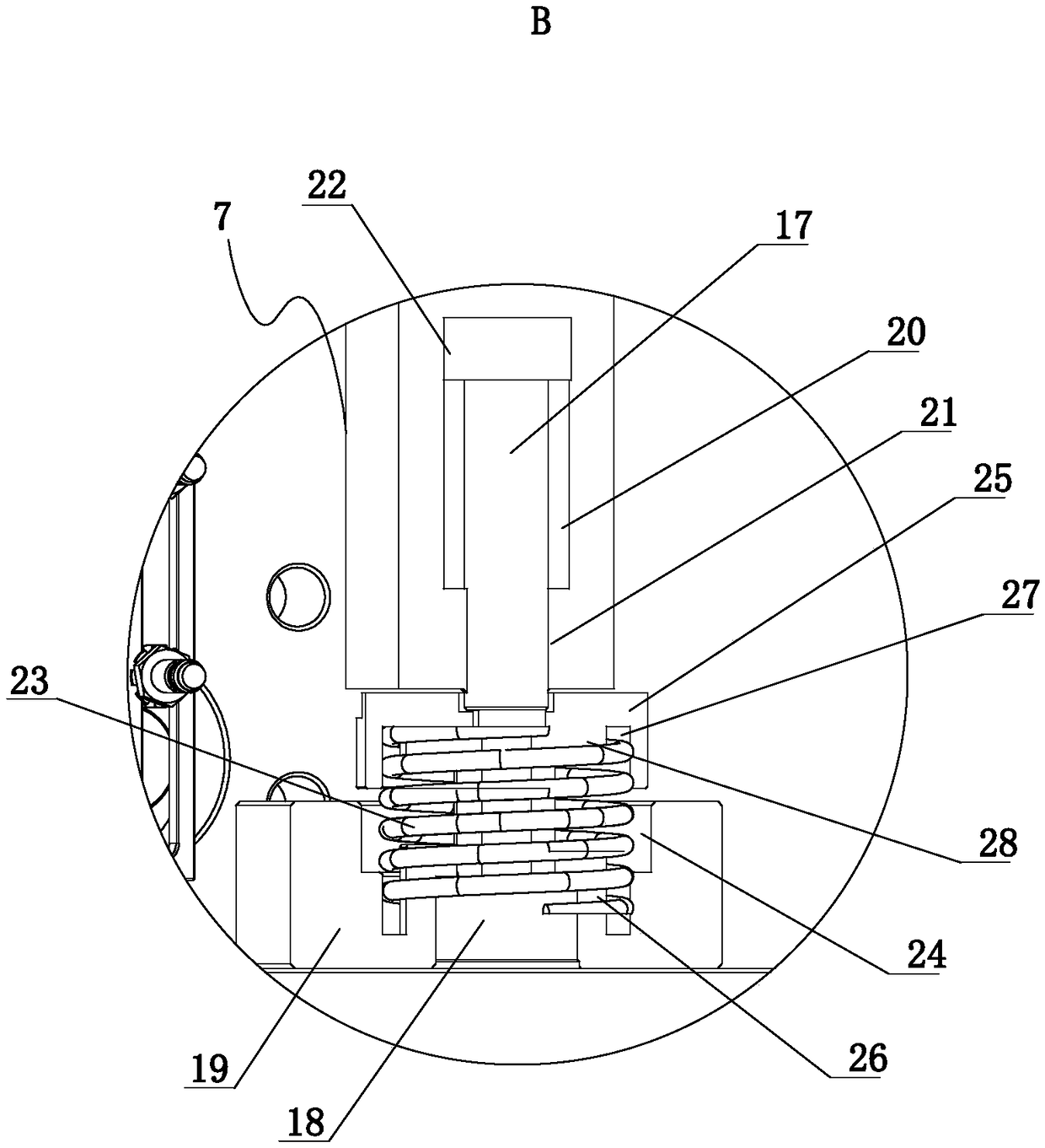
[0027] combine Figure 1-8 , a blowing needle seat mechanism for blow molding, which includes a lifting cylinder 1 fixed on the mold frame, a blowing needle seat 2 slidably connected to the mold frame, and a blowing needle 3 movably connected to the blowing needle seat 2 (of course It also includes other parts, but because it does not involve the invention of the present invention, so it will not be repeated here), one end of the lifting cylinder 1 is connected with the blowing needle seat 2 through the transverse partition 14, and the other end of the lifting cylinder 1 is connected to the mold frame connection, the lifting cylinder 1 controls the overall rise and fall of the blowing needle base 2, and the blowing needle base 2 includes a vertical back plate 4, a push-pull cylinder 5, a connecting rod 6, a push rod 7 and two parallel vertical side plates 8 , the vertical backboard 4 is located between two parallel vertical sideboards 8, and the two sides of the vertical backb...


PUM


Abstract

The invention discloses a blowing needle base mechanism for a blow molding die. The blowing needle base mechanism for the blow molding die comprises a lifting air cylinder (1), a blowing needle base (2) and a blowing needle (3), wherein the lifting air cylinder (1) is fixed on a die frame; the blowing needle base (2) is in sliding connection with the die frame; the blowing needle (3) is movably connected with the blowing needle base (2); the blowing needle base (2) comprises a vertical back plate (4), a push-and-pull air cylinder (5), a connecting rod (6), a push rod (7) and two parallel vertical side plates (8); one end of the connecting rod (6) is hinged with one vertical side plate (8), and the other end of the connecting rod (6) is positioned on the outer side of the other one of the vertical side plates (8); a piston rod of the push-and-pull air cylinder (5) is hinged with the other end of the connecting rod (6) through a first waist-shaped hole (9); one end of the push rod (7) isconnected with the blowing needle (3); the push rod (7) is parallel with the vertical side plates (8); and the middle part of the push rod (7) is hinged with the connecting rod (6) through a second waist-shaped hole (10). Compared with the prior art, the blowing needle base mechanism for the blow molding die has the characteristics of relatively small volume and low preparation cost.

Description

technical field [0001] The invention relates to the technical field of blowing needles for blowing molds, in particular to a blowing needle seat mechanism for blowing molds with relatively low preparation cost. Background technique [0002] Blow molding mainly refers to hollow blow molding (also known as blow molding), which is a method of blowing a hot-melt parison closed in a mold to form a hollow product by means of gas pressure. It is the third most commonly used plastic processing method, and at the same time It is also a fast-growing plastic molding method. The mold used for blow molding only has a female mold (concave mold). Compared with injection molding, the cost of equipment is lower, the adaptability is stronger, the formability is good (such as low stress), and products with complex undulating curves (shape) can be formed. . [0003] On the frame of the fuel tank blow molding mold, a lift cylinder is vertically installed at present, and a blow needle seat is f...

Claims


Application Information

Patent Timeline
Patent Type & Authority Applications(China)
IPC IPC(8): B29C49/60
CPCB29C49/60
Inventor 方永杰程利波程苗张修恩王锦浪钱鹏峰薛孟获陈聪王凯胡建飞蒋新通周华民
Owner 考泰斯(平湖)塑料技术有限公司
Why Eureka
Try Eureka