Heat dissipation wallboard

A wallboard and heat dissipation layer technology, applied in the field of wallboard design, can solve problems such as insufficient heat, potential safety hazards, and cracked wallboards, so as to prevent life loss and resource loss, solve energy waste, and achieve uniform distribution.

Pending Publication Date: 2019-01-08
ZHEJIANG HONGBO NEW BUILDING MATERIALS
View PDF7 Cites 0 Cited by
  • Summary
  • Abstract
  • Description
  • Claims
  • Application Information

AI Technical Summary

Problems solved by technology

[0002] With the development of modern intelligent furniture and comfortable furniture, people began to pursue the improvement of the quality of life. In winter, especially in the south, there is no heating. In order to make themselves have a comfortable living environment, people often install floor heating and other equipment at home A series of household heating measures also have corresponding heating for the wall, but the water heating or electric heating used for heating cannot fill the entire wall. If the wall is filled, it will not only cause a lot of consumption, but also cause a series of safety hazards. Therefore, the existing technology often adopts mosquito-repellent incense or S-type to lay heat sources. The advantage of this is to maximize the use of heat sources and ensure sufficient heat in the central area. This will inevitably lead to insufficient heat sources and insufficient heat in the surrounding areas. The uneven heating and cooling of the wallboard will lead to the cracking of the wallboard and the short life of the wallboard.

Method used


Image

  • Heat dissipation wallboard
  • Heat dissipation wallboard
  • Heat dissipation wallboard

Examples


Embodiment Construction

[0024] The present invention will be described in further detail below in conjunction with the accompanying drawings.

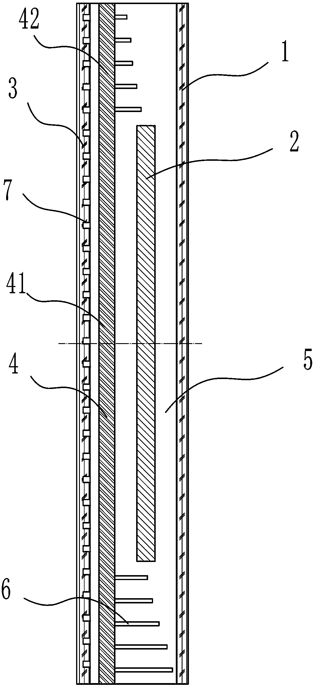
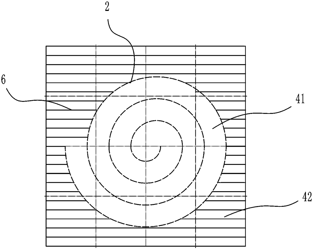
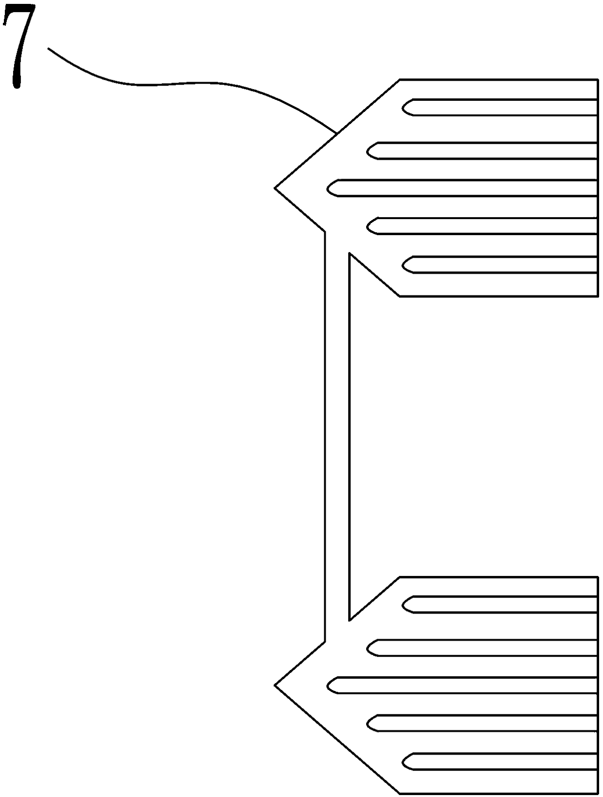
[0025] Such as figure 1 , 2 As shown in and 3, Embodiment 1, a heat dissipation wallboard, includes a wallboard base layer 1 and a heating device 2 arranged on one side of the wallboard base layer 1, and is characterized in that it also includes a wallboard surface layer 3 and a heat dissipation layer 4 , the wallboard surface layer 3 and the wallboard base layer 1 surround and form a wallboard cavity 5, the heating equipment 2 and the heat dissipation layer 4 are located in the wallboard cavity 5, and the heat dissipation layer 4 is arranged in the wallboard cavity 5 The heating equipment 2 is close to the side of the wall, and the heat dissipation layer 4 includes a heat absorption area 41 covering the heating equipment 2 and a heat release area 42 surrounding the heat absorption area 41. The heat release area 42 is provided with Heat dissipation fin grou...


PUM


Abstract

To solve the technical problems that heating of different heights in a room is not uniform, the service life of the wallboard is short and heat energy is consumed, the invention discloses a heat dissipation wallboard. The heat dissipation wallboard comprises a wallboard basic layer, heating equipment arranged on one side of the wallboard basic layer, a wallboard surface layer, and a heat dissipation layer, wherein the wallboard surface layer and the wallboard basic layer are used for surrounding to form a wallboard cavity; the heating equipment and the heat dissipation layer are located in thewallboard cavity; the heat dissipation layer is arranged on one side, close to the wall surface, of the heating equipment, and comprises an heat absorbing region covering the heating equipment and aheat emission region surrounding the heat absorbing region; a heat dissipation fin group is arranged on the heat emission region. According to the heat dissipation wallboard disclosed by the invention, through the heat dissipation layer, heating of the heating equipment which is originally located in the center is balanced and shared to every position of the room to the maximum degree; through thedistribution of heat dissipation fins of different lengths on the heat dissipation layer, certain heat quantity is transferred to different positions, so that the uniform distribution of the temperature of the room is realized, the defect that heated gas rise, so that the temperature of a position at a low sea level in the room is relatively low is made up, and the problem of energy waste is solved.

Description

technical field [0001] The invention relates to the technical field of wallboard design, in particular to a heat dissipation wallboard. Background technique [0002] With the development of modern intelligent furniture and comfortable furniture, people began to pursue the improvement of the quality of life. In winter, especially in the south, there is no heating. In order to make themselves have a comfortable living environment, people often install floor heating and other equipment at home A series of household heating measures also have corresponding heating for the wall, but the water heating or electric heating used for heating cannot fill the entire wall. If the wall is filled, it will not only cause a lot of consumption, but also cause a series of safety hazards. Therefore, the existing technology often adopts mosquito-repellent incense or S-type to lay heat sources. The advantage of this is to maximize the use of heat sources and ensure sufficient heat in the central ...

Claims


Application Information

Patent Timeline
Patent Type & Authority Applications(China)
IPC IPC(8): E04C2/52F24D3/14F24D13/02F24D19/04
CPCF24D3/148F24D13/024F24D19/04E04C2/525Y02B30/00
Inventor 林海明铁恒李彦宏
Owner ZHEJIANG HONGBO NEW BUILDING MATERIALS
Why Eureka
Try Eureka