Calculation method for atmospheric refractivity on electric wave ray

A technology of atmospheric refractive index and calculation method, which is applied in the field of radio wave refraction error correction, and can solve the problems of error, difficult to obtain atmosphere, large refractive index and so on.

Inactive Publication Date: 2019-01-08
HENAN NORMAL UNIV
View PDF5 Cites 4 Cited by
  • Summary
  • Abstract
  • Description
  • Claims
  • Application Information

AI Technical Summary

Problems solved by technology

[0005] In fact, the change of the atmosphere in the horizontal direction is difficult to obtain. If a limited amount of atmospheric refractivity is directly detected in the area where the radio wave ray passes, it will not only require a lot of manpower and material resources, but also it is impossible to obtain accurate horizontal change characteristics.
At present, almost all the radio wave refraction error corrections use the atmospheric layering method to obtain the one-dimensional profile of the atmospheric refractive index. It is an area with a complex underlying surface, and there will be a large refractive index error, which will affect the accuracy of radio wave refraction error correction

Method used


Image

  • Calculation method for atmospheric refractivity on electric wave ray
  • Calculation method for atmospheric refractivity on electric wave ray
  • Calculation method for atmospheric refractivity on electric wave ray

Examples


Embodiment Construction

[0056] The technical solution of the present invention will be clearly and completely described below in conjunction with the accompanying drawings. Apparently, the described embodiments are only some of the embodiments of the present invention, not all of them. Based on the embodiments of the present invention, all other embodiments obtained by persons of ordinary skill in the art without making creative efforts belong to the protection scope of the present invention.

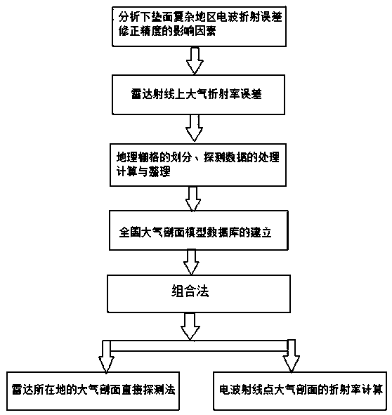
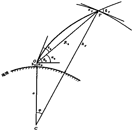
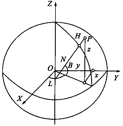
[0057] like figure 1 As shown, a method for calculating the atmospheric refractive index on a radio wave ray according to the present invention includes:

[0058] (1) According to the geographical range of our country and the characteristics of radio meteorological environment changes, the country is divided into 1840 grids by using the atmospheric environment grid technology, and the national atmospheric refractivity profile database is established;

[0059] The establishment of the National Atmospheric Refr...


PUM


Abstract

The invention discloses a calculation method for atmospheric refractivity on an electric wave ray, comprising the following steps: according to a geographic position range of China and characteristicsof radio meteorological environmental changes, building a nationwide atmospheric refractivity profile database; for a uniform atmospheric structure region, obtaining an atmospheric profile of a placewhere a radar is located by utilizing a direct detection method, and acquiring refractivity of the electric wave ray by virtue of translation of the actually measured refractivity at the same height;for a non-uniform atmospheric structure region, when a starting position of the electric wave ray is in a grid where the radar is located, obtaining an atmospheric refractivity profile of a place where the radar is located by utilizing the direction detection method; when the electric wave ray falls in other grids, firstly calculating a position of a ray point, then obtaining the atmospheric refractivity profile of the ray point by utilizing a nationwide atmospheric profile model database, and obtaining the atmospheric refractivity on the electric wave ray by utilizing the refractivity profile. The calculation method disclosed by the invention can be easily realized in engineering application, a calculation error of the calculation method is small, and then calculation accuracy of electric wave refractivity can be effectively improved.

Description

technical field [0001] The invention belongs to the technical field of electric wave refraction error correction, and in particular relates to a calculation method for atmospheric refraction index on electric wave rays. Background technique [0002] With the further improvement of the precision of electronic devices and the further development and optimization of signal and data processing methods, radar systems, which are indispensable in modern warfare, have been widely used. The detection accuracy of radar systems mainly depends on the correction accuracy of radio wave refraction errors. The radio wave refraction error is mainly caused by the radar wave passing through the uneven atmosphere. According to the current research and practical application of radio wave refraction error correction, the accuracy of the radio wave refraction error calculation formula itself is high, and the key factors affecting its correction accuracy are The accuracy of the atmospheric refracti...

Claims


Application Information

Patent Timeline
Patent Type & Authority Applications(China)
IPC IPC(8): G01S13/02G01S7/02
CPCG01S7/02G01S13/02
Inventor 张瑜秦元基李爽邢孟女赵小纳周文静
Owner HENAN NORMAL UNIV
Why Eureka
Try Eureka