A hand washing liquid automatic discharging device

An automatic discharge device, hand sanitizer technology, applied in household appliances, sanitary equipment, applications, etc., can solve the problems of easy adhesion to the nozzle, low degree of automation, residual virus, etc., to avoid the easy breeding of bacteria and residual viruses. , to achieve the effect of automation, hygienic and convenient use

Inactive Publication Date: 2019-01-11
贵州独山紫林山投资开发有限公司
View PDF0 Cites 4 Cited by
  • Summary
  • Abstract
  • Description
  • Claims
  • Application Information

AI Technical Summary

Problems solved by technology

[0002] At present, hand sanitizers are placed in the restrooms or toilets of tourist attractions, but in the prior art, when tourists wash their hands, the tourists directly press the nozzle on the hand sanitizer bottle with their hands to make the hand sanitizer flow out through the nozzle. However, in this process, since the tourists directly press the nozzle on the hand sanitizer with their hands, the hand sanitizer or water is easy to adhere to the nozzle during the tourists' use, which is inconvenient for the next tourist to press and discharge. Unhygienic shortcomings, and due to the large number of tourists in tourist attractions, after the nozzles of hand sanitizer are used by many people, bacteria and residual viruses are easy to breed on the nozzles, causing safety hazards to tourists, and the safety factor is low; For smaller tourists, it is difficult to press the nozzle on the hand sanitizer, resulting in inconvenient use and low degree of automation
[0003] To sum up, the prior art has the technical problems of inconvenient and unhygienic press discharge, easy breeding of bacteria and residual viruses on the nozzle, low safety factor, inconvenient use, and low degree of automation

Method used


Image

  • A hand washing liquid automatic discharging device
  • A hand washing liquid automatic discharging device
  • A hand washing liquid automatic discharging device

Examples


Embodiment Construction

[0018] The present invention will be further described below in conjunction with the accompanying drawings and embodiments, but not as a basis for limiting the present invention.

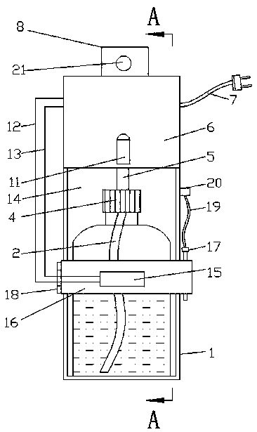
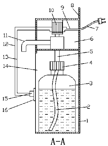
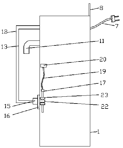
[0019] Example. A kind of hand sanitizer automatic discharge device, constitutes as Figure 1-4 As shown, it includes a housing 1, the housing 1 is provided with a fixing groove 14, the housing 1 on the side of the fixing groove 14 is movably connected with a fixing plate 16 via a rotating shaft 18, and an infrared sensor switch is arranged on the outside of the fixing plate 16 15. A hand sanitizer bottle 3 is movable in the fixed groove 14 of the housing 1, and the bottle mouth of the upper end of the hand sanitizer bottle 3 is movably connected with a bottle cap 4 through a thread 25, and the bottle cap 4 is movably connected with a liquid inlet pipe 5, and the bottle cap 4 The outside of the liquid inlet pipe 5 at the lower end is provided with an annular stopper 24, the lower end of the liquid ...


PUM


Abstract

The invention discloses a hand washing liquid automatic discharging device, which includes a housing, stationary groove are arranged on the housing, A fixing plate is movably connected to the housingon one side of the fixing groove through a rotating shaft, An infrared induction switch is arranged on the outside of the fixing plate, a hand washing liquid bottle is movably arranged in a fixed groove of the housing, the bottle mouth of the upper end of the hand-washing liquid bottle is movably connected with a bottle cap through threads, A liquid inlet pipe is movably connected to that bottle cap, an annular limiting block is arrange on the outer side of the liquid inlet pipe at the lower end of the bottle cap, a liquid inlet pipe is connected to the lower end of the liquid inlet pipe, a liquid inlet chamber is arranged on the upper end housing of the liquid inlet pipe, the liquid inlet pipe is connected with a water pump, the water pump is fixedly connected with the liquid inlet chamber, and the water pump is connected with a liquid outlet pipe; The pump is connected with a first conductor and a second conductor, and the second conductor is connected with an infrared induction switch. The present invention has the advantages of automatic discharging, sanitary and convenient use of hand washing liquid, avoiding easy breeding of bacteria and residual virus on the sprinkler head,high safety factor and high automation degree.

Description

technical field [0001] The invention relates to a discharging device, in particular to an automatic discharging device for hand sanitizer. Background technique [0002] At present, hand sanitizers are placed in the restrooms or toilets of tourist attractions, but in the prior art, when tourists wash their hands, the tourists directly press the nozzle on the hand sanitizer bottle with their hands to make the hand sanitizer flow out through the nozzle. However, in this process, since the tourists directly press the nozzle on the hand sanitizer with their hands, the hand sanitizer or water is easy to adhere to the nozzle during the tourists' use, and it is inconvenient for the next tourist to press and discharge the material. Unhygienic shortcomings, and due to the large number of tourists in tourist attractions, after the nozzles of the hand sanitizer are used by many people, bacteria and residual viruses are easy to breed on the nozzles, causing safety hazards to tourists, an...

Claims


Application Information

Patent Timeline
Patent Type & Authority Applications(China)
IPC IPC(8): A47K5/12
CPCA47K5/1211A47K5/1217
Inventor 莫应勤何道欣
Owner 贵州独山紫林山投资开发有限公司
Why Eureka
Try Eureka