Massage chair and massage movement thereof

A technology of movement and walking motor, which is applied in the direction of kneading and massage equipment, auxiliary products for massage, equipment for passive exercise, etc., and can solve the problems of increasing discomfort

Pending Publication Date: 2019-01-11
HENGLIN HOME FURNISHINGS CO LTD
View PDF0 Cites 3 Cited by
  • Summary
  • Abstract
  • Description
  • Claims
  • Application Information

AI Technical Summary

Problems solved by technology

However, when the shoulder and neck need to be massaged at the same time, due to the structure of the shoulder and neck, the massage method needs to be carried out in a kneading manner similar to the opening and closing of two fingers of a person. Massaging the shoulders and neck will increase the discomfort, which can only be counterproductive. Therefore, the above massage devices are not suitable for the shoulders and neck

Method used


Image

  • Massage chair and massage movement thereof
  • Massage chair and massage movement thereof
  • Massage chair and massage movement thereof

Examples


Embodiment 1

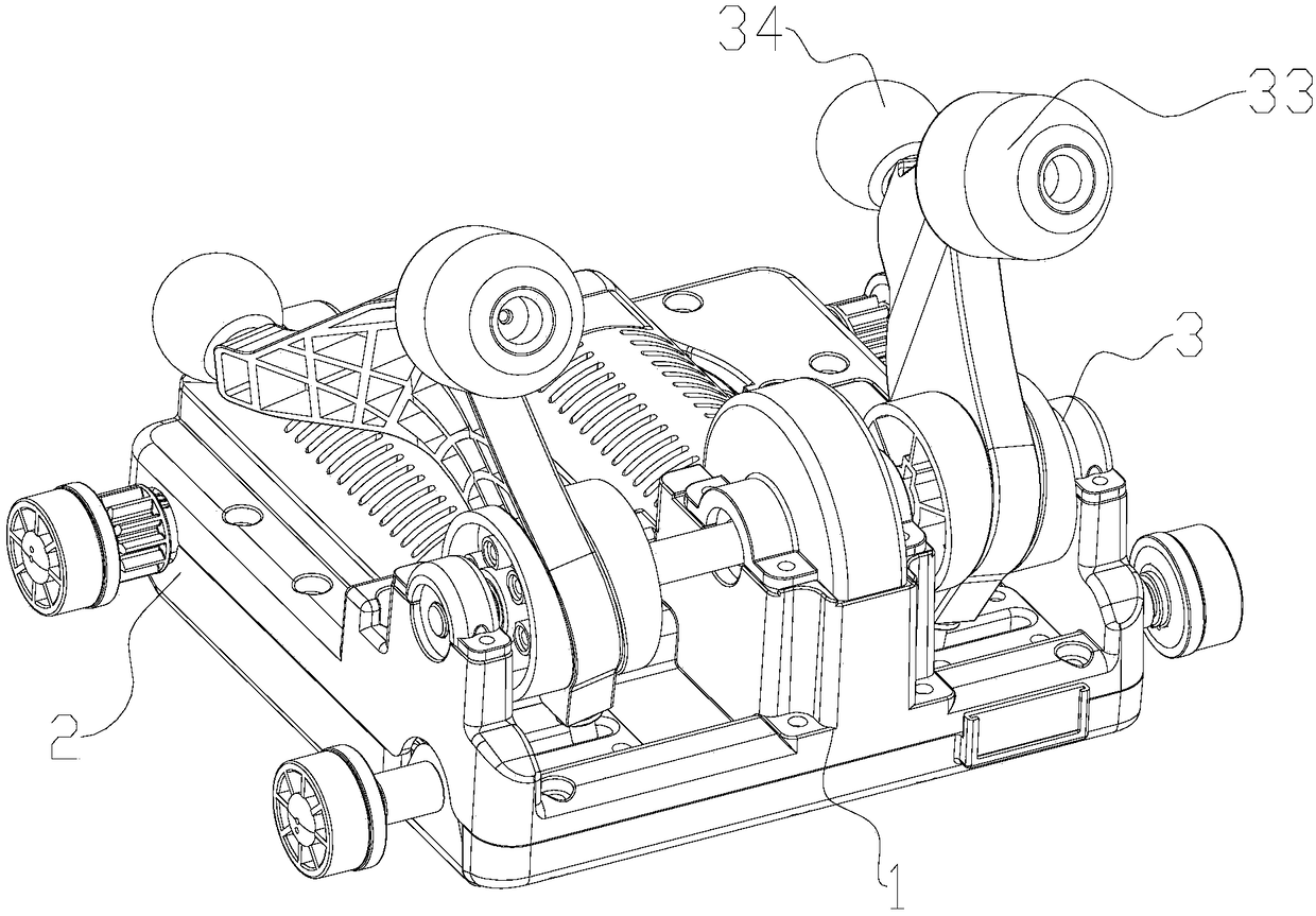
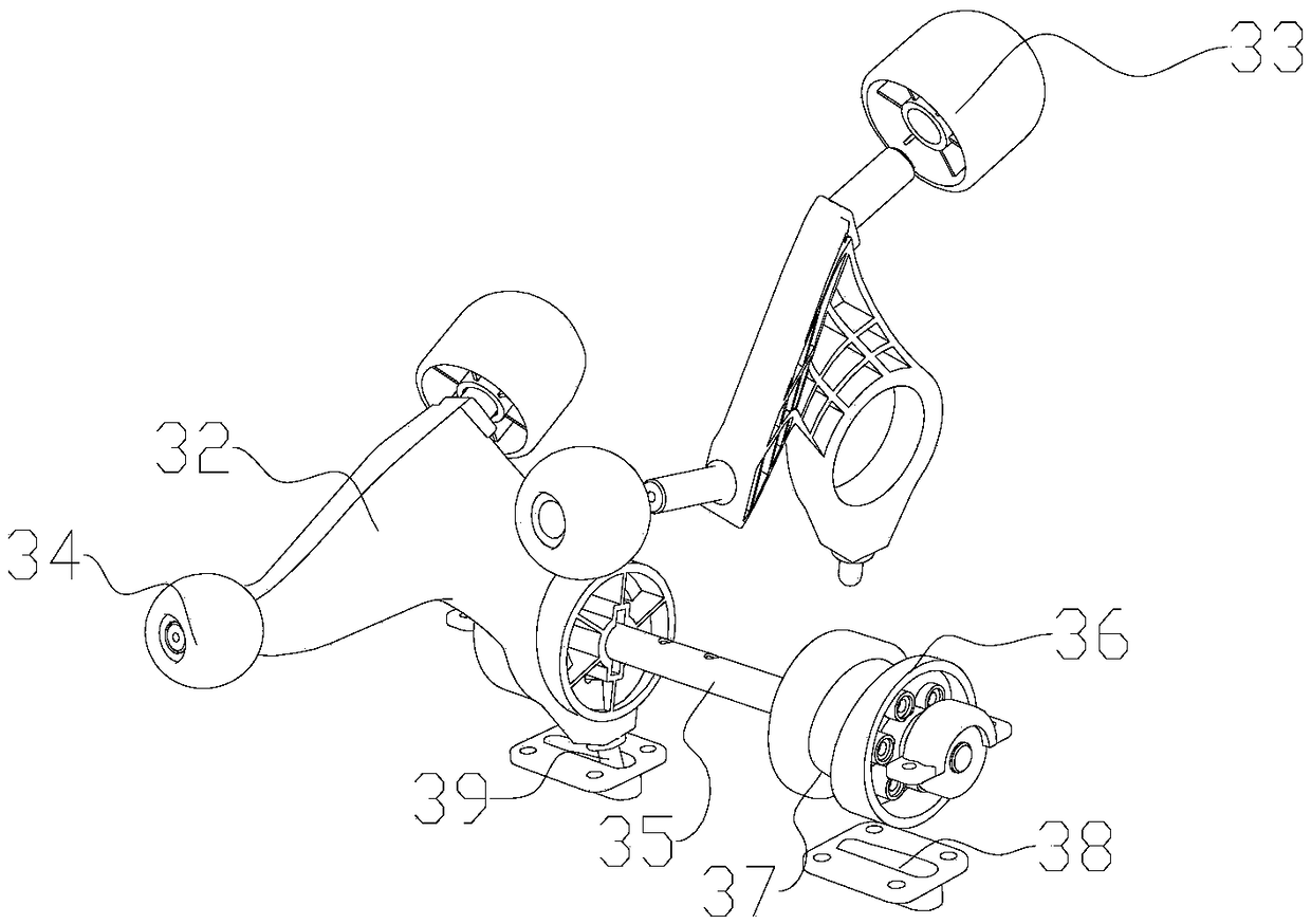
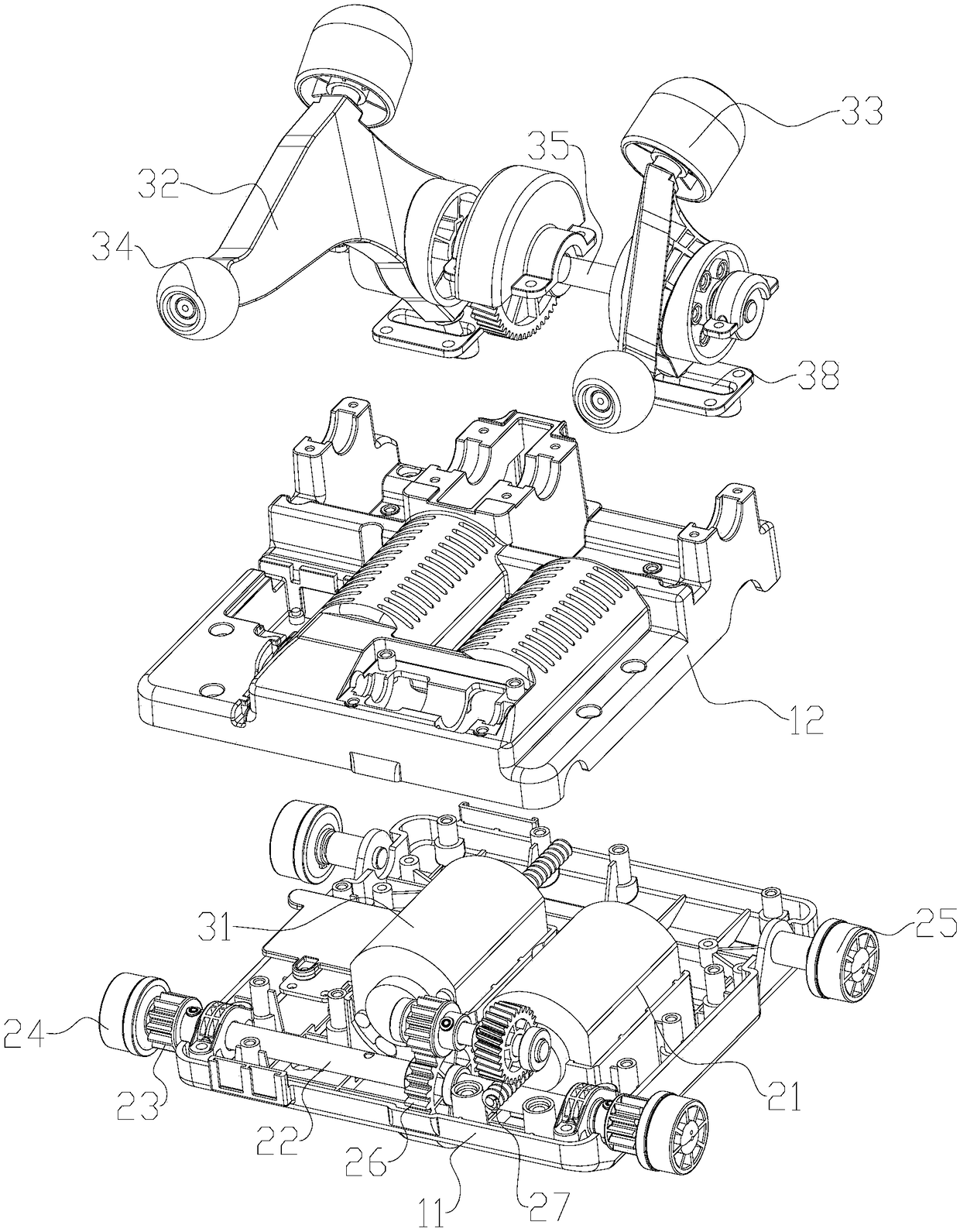
[0023] Such as Figure 1~3 The shown massage mechanism includes a housing 1 , and a walking device 2 and a massage device 3 arranged on the housing 1 . The housing 1 includes a lower housing 11 and an upper housing 12 , and the upper housing 11 covers the lower housing 12 to form a housing inner chamber.

[0024] Described walking device 2 comprises traveling motor 21, and the traveling transmission shaft 22 driven by traveling motor 21, and the traveling drive tooth 23 and traveling drive wheel 24 that are connected on the two ends of traveling transmission shaft 22, and the housing that is positioned at 1 on the walking driven wheel 25. Specifically, the traveling transmission shaft 22 is positioned in the casing 1 through bearings, and its two ends are outside the casing 1 , and the traveling driving gear 23 and the driving driving wheel 24 are outside the casing 1 . The output shaft of the traveling motor 21 is a worm shaft, and the middle part of the traveling transmiss...

Embodiment 2

[0029]This embodiment relates to a massage chair, which includes a seat, on which a curved track is installed, and a massage movement as described in Embodiment 1 is provided for moving along the curved track. The curved track is composed of two supporting rails arranged parallel to each other and left and right symmetrically connected by a plurality of cross bars, and racks are installed on the supporting rails; the supporting rails include head and neck sections corresponding to the head and neck of the human body, The backrest section corresponding to the back of the human body, the waist-hip section corresponding to the waist and buttocks of the human body, and the leg section corresponding to the thigh of the human body, the head and neck section is a straight section extending forward, and the head and neck section and the backrest section have a V-shaped structure , and the V-shaped bottom is connected through a circular arc transition, the waist-hip section is in an S-s...


PUM


Abstract

The invention relates to the field, in particular to a massage chair and a massage movement thereof. The massage movement comprises a housing, a walking device and a massage device arranged on the housing, wherein the massage device comprises a massage motor and two groups of massage arms driven by the massage motor. When the two massage arms swing and are relatively close to or far away from eachother; the two groups of massage arms form an eight-shaped shape which conforms to the physiological curve of the neck and shoulder of the human body, and the two sides of the free end of the massagearm are respectively positioned with a neck massage ball and a shoulder massage ball through a rotating shaft; the neck massage ball is arranged at the eight-shaped closing end, and the rotation axisof the neck massage ball is perpendicular to the swing path of the closing end of the swing arm; the shoulder massage ball is located at the wide-mouth end of an eight-shaped shape, and the rotationaxis of the shoulder massage ball is perpendicular to the swing path of the wide-mouth end of the swing arm. The massage movement can simultaneously massage the neck and the shoulder of the user respectively, and the massage comfort is higher.

Description

technical field [0001] The invention relates to the field of massage machines, in particular to a massage chair and a massage movement thereof. Background technique [0002] In modern urban life, people's pace of life is getting faster and faster. Most people have to bury their heads in a lot of work during the day, and at night they have to take care of their children and do housework and other tasks. After a busy day, they only have a short time to rest; Muscle and bone strains and other physical problems caused by fatigue, if not relieved in time, will inevitably lead to irreversible consequences if they are not resolved for a long time, which will have a great impact on the future body. [0003] For this reason, tools such as various massagers, massage chairs appear on the market today, and people can massage the body by means of these massage devices, thereby reaching the purpose of promoting blood circulation and relaxing the body and relieving fatigue. However, the ...

Claims


Application Information

Patent Timeline
Patent Type & Authority Applications(China)
IPC IPC(8): A61H1/00A61H7/00
CPCA61H1/008A61H7/007A61H2201/0149A61H2201/1207A61H2205/04A61H2205/062
Inventor 王江林
Owner HENGLIN HOME FURNISHINGS CO LTD
Why Eureka
Try Eureka