
A method for installing a decompression chamber and a transition chamber of a saturation diving ship

A technology of decompression chamber and installation method, which is applied in transportation and packaging, ship construction, ship design, etc. It can solve the problem of difficulty in ensuring the level of decompression chamber and transition chamber of saturated diving boats, shorten the installation time, and reduce the difficulty of installation, etc. problem, achieve the effect of shortening installation time, reducing installation difficulty and saving installation cost

Active Publication Date: 2019-08-27
广州黄船海洋工程有限公司
View PDF3 Cites 0 Cited by
  • Summary
  • Abstract
  • Description
  • Claims
  • Application Information

AI Technical Summary

Problems solved by technology

[0004] The purpose of the present invention is to overcome the shortcomings of the prior art, to provide a method for installing the decompression chamber and transition chamber of a saturation diving ship, and to solve the problem that it is difficult to ensure the level of the decompression chamber and transition chamber of a saturation diving ship during installation. Compared with the conventional installation method of leveling with steel pads, it reduces the difficulty of installation, shortens the installation time and saves installation costs

Method used


Image

  • A method for installing a decompression chamber and a transition chamber of a saturation diving ship
  • A method for installing a decompression chamber and a transition chamber of a saturation diving ship
  • A method for installing a decompression chamber and a transition chamber of a saturation diving ship

Examples


Embodiment Construction

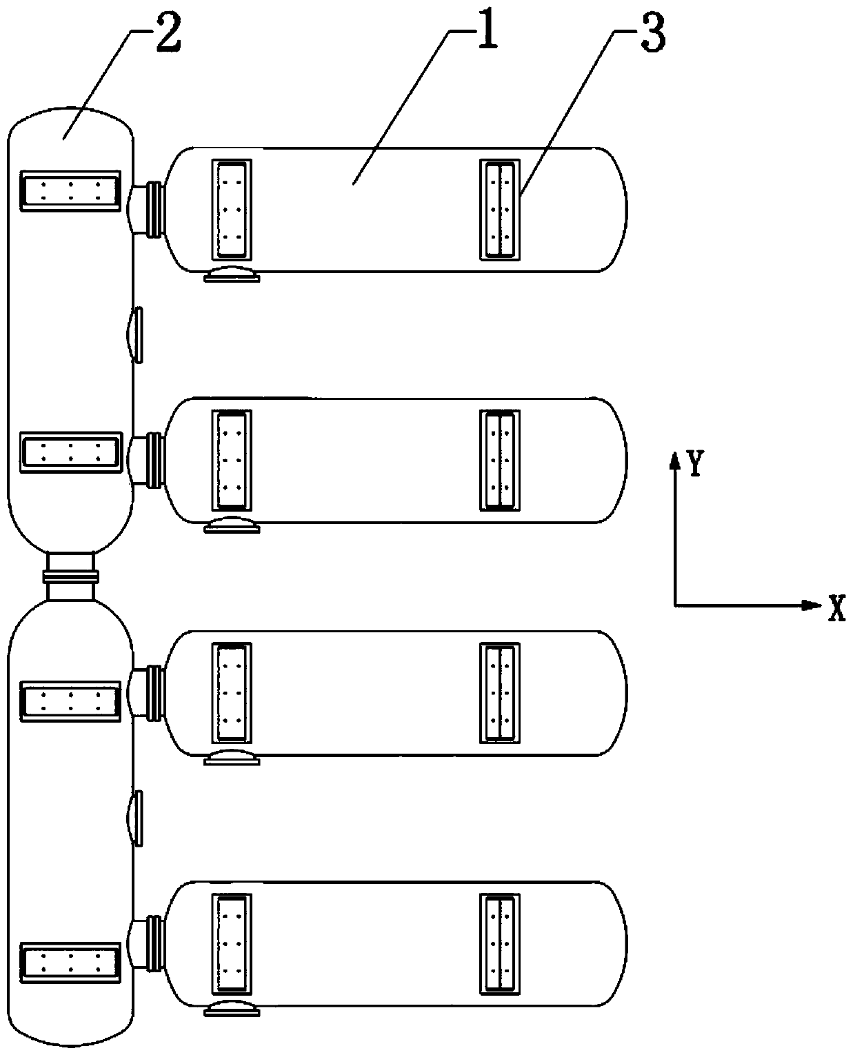
[0026] The present invention will be further described below in conjunction with the accompanying drawings, but the protection scope of the present invention is not limited to the following description.

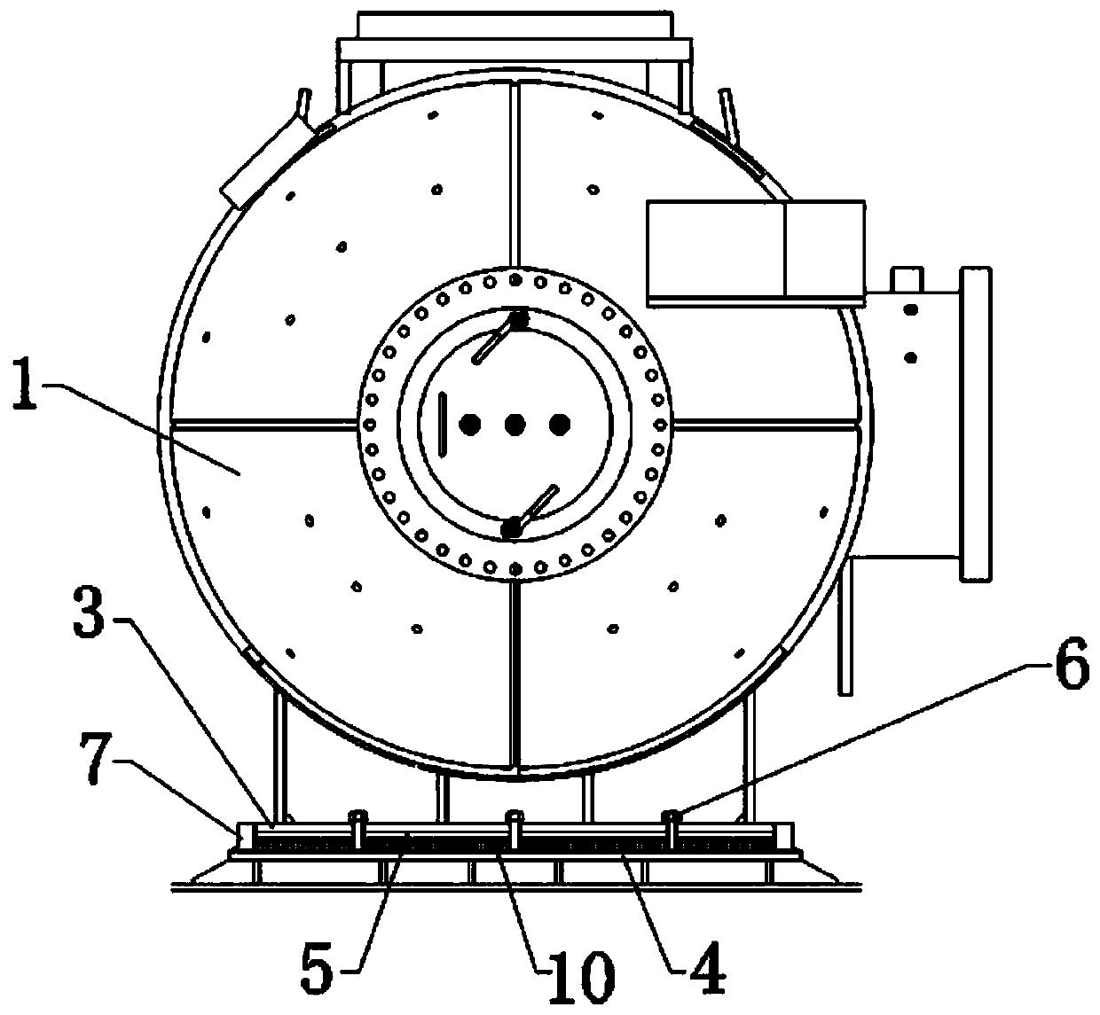
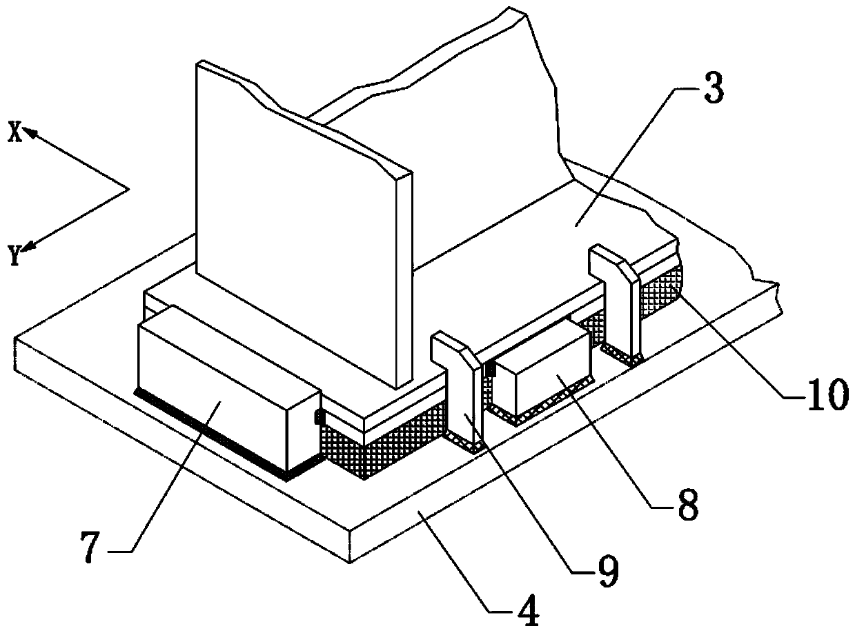
[0027] Such as Figure 1 to Figure 5 Shown, a kind of installation method of decompression chamber and transition chamber of saturation diving ship comprises the following steps:

[0028] S1. Mark the line and install the base 4: as figure 2 with Figure 4 As shown, the bottoms of the decompression chamber 1 and the transition chamber 2 are respectively provided with bases 3, and according to the installation drawings of the decompression chamber 1 and the transition chamber 2, determine the position of the base 4 on the deck, draw a line on the deck, And fixedly install the base 4 in the marked area, so that the base 4 corresponds to the base 3 of the pressure and decompression cabin 1 and the transition cabin 2 respectively;

[0029] S2. Preinstall the pressure plate 5:...


PUM


Abstract

The invention relates to a method for installing compression and decompression chambers and a transition chamber of a saturated submersible ship, comprising the following steps: S1, marking and installing a base; S2, pre-assembling a pressing plate; S3, leveling; S4, mounting an X-direction thrust block, a Y-direction thrust block and a 7-shaped pressing block: welding the X-direction thrust block, the Y-direction thrust block and the bottom surface of the 7-shaped pressing block on the base, and respectively welding the side surfaces of the X-direction thrust block and the Y-direction thrustblock on the side walls of the pressing plate, wherein the upper end of the 7-shaped pressing block is pressed on the upper surface of the base, and the side walls of the 7-shaped pressing block and the side walls of the pressing plate and the base are respectively provided with a gap, and the compression and decompression chambers can be slightly displaced in the X-direction and the transition chamber can be slightly displaced in the Y-direction; and S5, performing infusion of epoxy layer. The method for installing compression and decompression chambers and a transition chamber of a saturatedsubmersible ship solves the technical problem that the compression and decompression chambers and the transition chamber of the saturated submersible ship are difficult to ensure the level when beinginstalled, reduces the installation difficulty, shortens the installation time and saves the installation cost compared with the conventional installation method of leveling with the steel cushion block.

Description

technical field [0001] The invention relates to the technical field of ship equipment installation, in particular to a method for installing a decompression chamber and a transition chamber of a saturation diving ship. Background technique [0002] The divers of the saturation diving boat carry out the transition cabin after pressurizing the decompression cabin, enter the diving operation from the transition cabin, and leave the cabin after the decompression of the addition and subtraction cabin when returning, and evacuate directly from the transition cabin to the high-pressure escape boat in case of emergency , The pressure and decompression chamber and the transition chamber are installed with interface alignment requirements, and the installation accuracy is required to be high. At the same time, the pressure and decompression chamber and the transition chamber need to maintain a small amount of displacement in a different direction after the installation is completed, an...

Claims


Application Information

Patent Timeline
Patent Type & Authority Patents(China)
IPC IPC(8): B63B3/13B63B9/00
CPCB63B3/13B63B71/00
Inventor 冯仕清李云军马可梁剑明
Owner 广州黄船海洋工程有限公司
Learn More