Multi-functional storage box
A storage box and multi-functional technology, applied in the field of storage boxes, can solve the problems of accidental collision, damage, falling of the storage box, etc., and achieve the effect of convenient disassembly and assembly, space saving, safe and stable placement or handling
- Summary
- Abstract
- Description
- Claims
- Application Information
AI Technical Summary
Problems solved by technology
Method used
Image
Examples
Embodiment 1
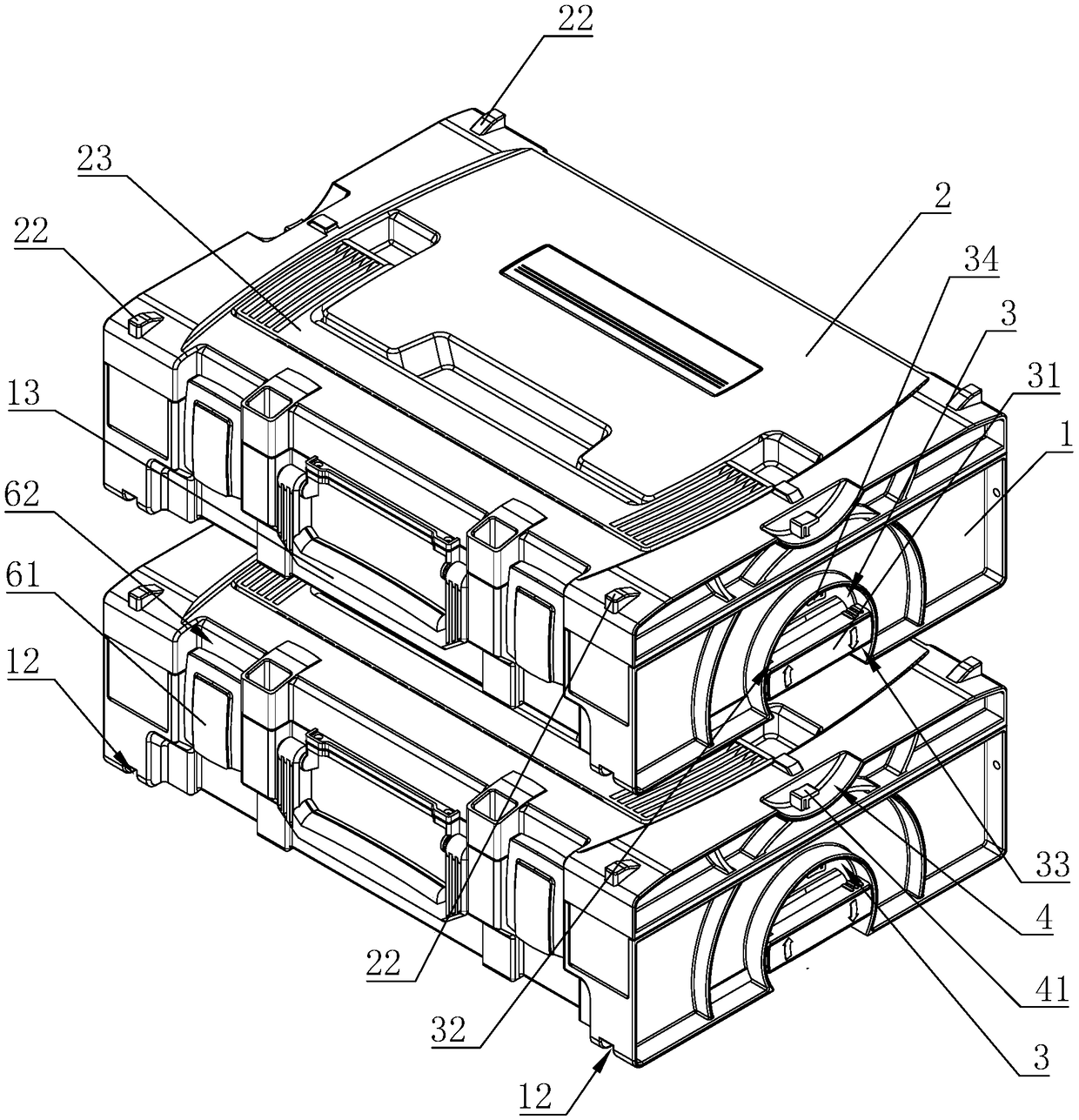
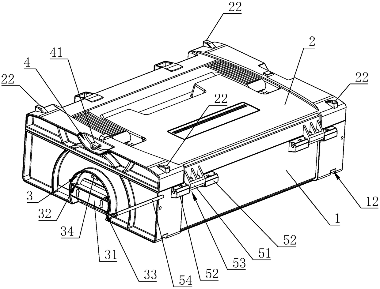
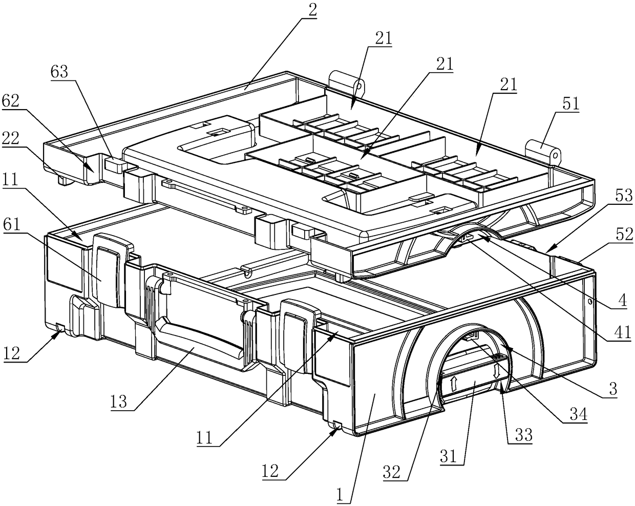
[0018] Embodiment 1: A multifunctional storage box, including a box body 1 and a box cover 2 arranged on the box body 1, a movable locking mechanism is arranged between the box body 1 and the box cover 2, and the movable locking mechanism includes a positioning cavity 3 And connecting chamber 4, rotation in the positioning chamber 3 is provided with a rotary lock button 31, one end of the rotary lock button 31 is provided with a first lock hole 32, and the other end of the rotary lock button 31 is provided with a second lock hole 33, positioning The cavity 3 is provided with a first locking hook 34 which is rotated and locked with the first locking hole 32 , and the connecting cavity 4 is provided with a second locking hook 41 which is rotated and locked with the second locking hole 33 .
[0019] The positioning chamber 3 is located below the side of the casing 1, the first locking hook 34 is located at the top of the wall of the positioning chamber 3, the first locking hole 32...
Embodiment 2
[0020] Embodiment 2: The remaining parts are the same as Embodiment 1, the difference is that the positioning chamber 3 is located above the side of the case cover 2, the first lock hook 34 is located at the lower part of the wall of the positioning chamber 3, and the first lock hole 32 is located at the bottom of the rotating shaft. The lower surface of one end of the locking button 31, the second locking hole 33 is located on the upper surface of the other end of the rotary locking button 31, the connecting chamber 4 is located below the side of the casing 1, and the second locking hook 41 is located at the bottom of the connecting chamber 4. upper cavity wall.
Embodiment 3
[0021] Embodiment 3: The remaining parts are the same as in Embodiment 1, the difference is that the lower surface of the case cover 2 is provided with a working surface 21, and a locking mechanism located at the front of the case body 1 is provided between the case body 1 and the case cover 2 And be positioned at the detachable rotary connection mechanism of casing 1 rear portion, detachable rotary connection mechanism comprises the rotary connection block 51 that is arranged on the case cover 2 and the rotary connection seat 52 that is arranged on the box body 1, and the rotary connection seat 52 A rotating connection groove 53 and a rotating shaft 54 are provided. The rotating shaft 54 detachably passes through the rotating connecting seat 52 and the rotating connecting groove 53 transversely. The rotating connecting block 51 extends into the rotating connecting groove 53 and is rotatably arranged on the rotating shaft 54. superior.
PUM
 Abstract
Description
Claims
Application Information
 - R&D
- Intellectual Property
- Life Sciences
- Materials
- Tech Scout
- Unparalleled Data Quality
- Higher Quality Content
- 60% Fewer Hallucinations
Browse by: Latest US Patents, China's latest patents, Technical Efficacy Thesaurus, Application Domain, Technology Topic, Popular Technical Reports.
© 2025 PatSnap. All rights reserved.Legal|Privacy policy|Modern Slavery Act Transparency Statement|Sitemap|About US| Contact US: help@patsnap.com


